Каталог Iscar дисковые фрезы и фрезерные пластины 2022 - страница 62
Навигация
 Каталог Iscar крепление инструмента
 Каталог Iscar инструмент для обработки отверстий
 Каталог Iscar резьбонарезные фрезы
 Каталог Iscar инструмента для сверления
 Каталог Iscar решения для глубокого сверления
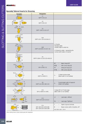
SLOTTING & SLITTING CUTTERS USER GUIDE Specially Tailored Inserts for Grooving Examples Designation R0.25 TYP. E1 4.0 GSFP-4.00-0.25 R1.65 R4.0 E2 3.30 3.95 GSFP-3.95-4.00 1.98 R0.30 R0.05 E3 3.5 GSFP-1.98-0.3-0.05-3.5T 5.28 4.10 R1.2 R0.0 E4A GSFP-5.28-1.20-0.00-25A4.10 25° 5.28 A–Chamfer R0.0 4.10 Preceding digits: R1.2 E4B Chamfer angle to center line GSFP-5.28-25A4.10-0.00-1.20 A–Followed by digits - representing the 25° nominal width location of chamfer 5.28 4.10 2.05 R0.0 R0.2 E5 GSFP-5.28A4.10-0.00-0.20-45A2.05 25° 45° MT – Metric thread 60º R0.15 E7 MT – With corner radius 4.4 60° GIP-4.4-MT-0.15 WT – Whitworth thread 55º WT – With corner radius R0.15 5.4 90° E8GSFP-5.4-90V0.15 V– V shape inclusive angle(Blank width 5.4 not rectified) R0.35 TYP. 1.82 29° E9GSFP-4.40-29V1.82K-0.35K– Frontal straight width of trapezoid(Width 4.40 rectified) 4.4 10° 50° 80° E10 V shape 80º at 10º slant angle 5.4 R0.1 40° GIP-5.4-80V0.10-10RS (Blank width 5.4 not recitifed) 15° R0.0 LA – Lead angle Lefthand E13 3.10 4.0 GSFP-4.00-0.00-0.30-5LA R0.10 TYP. 5° R0.3 RA – Lead angle Righthand 4.5 0.2 T – Depth of groove (nominal)E14 1.98 T GIP-1.98-0.00-4.50T0.20B B – Break corners width of chamfers, 45ºGFP-1.98-0.00-4.50T0.20B R0.00 TYP. Note: Blank width > 2B+W When ordering inserts, include carbide grade with designation. 378 ISCAR