Общий каталог D'andrea 2022 - страница 113
Навигация
 Общий каталог D'ANDREA 2018
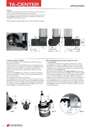
486 1463.6 20 + 00.01 == 60 == 45° TA-CENTER APPLICATION U-Drive D’ANDREA has developed a standard U-DRIVE drive unit (horizontal and at 90°), on which different types of motors can be fitted. The U-DRIVE can be easily positioned on the machine (see photo) with a support (18) plate adaptor to the machine connected and fasted to the holes (C) on the front of the spindle. Other special configurations can be provided on request. Ø 6.2 22 + 0.1 0 Ø5 15.5 5 H7 C 18 6 42 32 25 45 55.5 15 70.5 38.5 60 103.5 27 U-DRIVE assembly TA-CENTER The driving flange (24) must point towards the centre For a correct installation of the U-DRIVE and TA-CENTER, carefully of the spindle. follow these instructions: 3. To align the TA-CENTER to the U-DRIVE, remove the two locking 1. Mount the cone on the TA-CENTER, detect the B distance between dowels (21) of the orientation ring (8) to the left and right of the white the gauge limit of the cone (4) and the retaining pin plane (9). Calculate reference point, and replace them temporarily with two longer dowels, X height with the formula X=B+4 mm. Warning, if more heads are integrating the ring to the fixed body. Screw the 4 ring dowels until they employed on the same machine, calculate the X height by using the lay slightly to the cone (4) (pic.1-2). lower B value. After checking that the head is in the HOME POSITION, that the slide 2. Mount the plate (18) and the U-DRIVE on the machine according to stroke is 0 and that the transmission shaft (22) of the U-DRIVE is aligned the Layout and detect the F distance between the spindle gauge limit with the retaining pin (9) of the head, spindle orientation (M19), manually and the U-DRIVE plane. mount the head in the machine. Insert the cone (4) in the spindle by The F distance must be equal to the X height. rotating the fixed body (1) up to the U-DRIVE, once the TA-CENTER and The plate (18) is thicker than indicated in the layout, to get the F and X U-DRIVE are aligned, lock the TA-CENTER in the machine and tighten distances alike, the plate thickness must be trimmed (18). After adjusting all dowels (21) putting the two original dowels one at a time. During this the F height, remount the U-DRIVE by paying attention to its alignment, operation, pay attention to the height between the ring (8) and the fixed the position of the drive shaft (22) and distance (23) between the drive body (1) (pic.3). Load and unload the TA-CENTER manually a few times shaft axis (22) and the machine spindle centre. to check the alignment. 4 4 8 D D 21 8 8 21 1 0.5 1 pic.1 pic.2 7 pic.3 6 TA-C 80 112