Общий каталог D'andrea 2022 - страница 114
Навигация
 Общий каталог D'ANDREA 2018
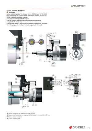
I= 65 / 80 / 110 ± 0.02 5 Ø 11 Ø 13 22 Ø 20 -- 0.02 0.01 10 5 ) APPLICATION U-DRIVE assembly TA-CENTER WARNING During tool changes the “A” shafts of the TA-CENTER and “A1” U-DRIVE must comply with the correct “HOME POSITION” position, must be run always in unidirectional way to allow : • the perfect coupling tooth “A” to “A1”. • can be properly attached, the rotating body can be properly coupled to the fixed body • Recognition of the “0” position of the tool slide should occur, otherwise it is likely to pass the limit and cause damage inside the head. X ) p. 115 20+ 0.01 0 = = A1 A B 4 + 0.3 0 19 A1 A 4.5 5 22 24 23 4 L p. 115 7 0.5 (F +00.3) 7 6 TA-C 80 7 19 17 TA-C 80 A1 19 4 + 0.3 0 A 15 18 0.5 4.5 5 7 9 20 L) p. 115 21 8 15. Air inlet connection for cleaning the drive 1/8 GAS. 18. Support plate for blocking and adapting the X dimension of the U-DRIVE ( X +0.3 0 ) mm. 19. Release rotation lock travel. 20. Locking-unlocking lever. 113