Общий каталог D'andrea 2022 - страница 112
Навигация
 Общий каталог D'ANDREA 2018
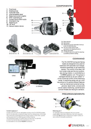
COMPONENTS 1. Fixed body 2. Rotating body 3. Toolholder slide4.Interchangeable taper 11 5. Balancing counter-weights 6. MHD’ expanding pin 7. Coolant liquid outlet nozzle 8. Orientation ring 10 A 9. Retaining pin 8 9 10. “A” drive 511. Manual rotation device 6 4 3 2 7 1 12. Base element 13. Servomotor 14. Mechanical unit for automatic hook-up to the TA-CENTER drive 15. The unit comes with air inlet connection for cleaning the drive 16. Manual lubrication 17. n°6 M5x8 holes to be used for securing 14 15 16 17 12 13 14 15 16 17 12 13 13 14 15 16 17 12 a possible protective casing COMMAND The TA-CENTER boring and facing heads are designed to be used on machines with automatic tool change, therefore essentially on all machining centers. The control of the feed, the tool-holder slide and the tool position, also during rotation, is controlled by a CNC U-DRIVE gearbox unit. This group ismanaged directly by an axis called “U” of the numerical control of the machining center. A machining center set up in this way allows to hit several different features such as internal and external turning, U-DRIVE grooves, taper bores, concave and convex radius machining, cylindrical and TA-C conical threads and facing for serration. PREARRANGEMENTS pic.1 pic.2 5 3 Coolant supply pic.1 Balancing pic.2 Coolant exits from the two adjustable nozzles in the TA-CENTER located TA-CENTER heads are designed with two counter- next to the slide after crossing the taper and the rotating body of the head. weights (5) for automatic balancing, that move opposite This noteworthy advantage ensures longer duration of the insert, quicker to the slide (3) allowing to machine at a higher number of cutting speed and for obtaining good surface finishes. rpms without noticeable oscillations. The centralized supply of coolant does not harm the TA-CENTER of which the internal labyrinth protected by an O-ring. It is advisable to not exceed 40 BAR of pressure. 111