Общий каталог Sumitomo 2018 - 2019 - страница 564
Навигация
- Pages 3-6_CS6_EN_web
- A 1-20 insert selection EN_web
- B 1-14 grades_EN_web
- C01-17 inserts intro pages_EN_web
- C18-56 negative inserts_EN_web
- C57-86 positive inserts_EN_web
- D 1-46 tool holders_EN_web
- E 1-24 boring bars_EN_web
- F 1-48 grooving_thread tools_EN_web
- G 1-54 milling cutters_EN_web
- H 1-48 insert type endmills_EN_web
- J 1-24 new endmills_EN_web
- J 25-50 endmills_EN_web
- K 1-46 Multi-Drills_EN_web
- K 47-76 Multi-Drills_EN_web
- L 1-28 cbn_pcd grades_EN_web
- M 1-34 cbn_pcd inserts_EN_web
- M 35-56 SHM tools_EN_web
- N1-24 technical guidance_EN_web
- P 1-8 spare parts_neu_EN_web
- P 9-22 index_notes_EN_web

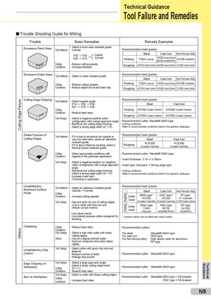
Cutting Edge FailureOthers RoughingFinishing Technical Guidance Tool Failure and Remedies Trouble Shooting Guide for Milling Trouble Basic Remedies Remedy Examples Excessive Flank Wear - Select a more wear resistant grade.Tool MaterialCarbide- Recommended insert grades P30K20a P20a K10a{ CoatedCermet Steel Cast Iron Non-Ferrous AlloyFinishingT250A (Cermet)ACK200 (Coated Carbide)BN700 (SUMIBORON)DA1000 (SUMIDIA) Cutting - Reduce cutting speeds.Conditions- Increase feedrate.Roughing ACP100 (Coated Carbide) ACK200 (Coated Carbide) DL1000 (Coated Carbide) Excessive Crater Wear Tool Material - Select a crater resistant grade. - Recommended insert grades Steel Cast Iron Non-Ferrous Alloy Cutting - Reduce cutting speeds. Finishing T250A (Cermet) ACK200 (Coated Carbide) DA1000 (SUMIDIA) Conditions - Reduce depth-of-cut and feed rate. Roughing ACP100 (Coated Carbide) ACK200 (Coated Carbide) DL1000 (Coated Carbide) Cutting Edge Chipping Tool Material - Select tougher grade. - Recommended insert grades P10 a P20 a P30 Steel Cast Iron K01 a K10 a K20 Cutting Finishing ACP200 (Coated Carbide) ACK200 (Coated Carbide) Conditions - Reduce feed rates. Roughing ACP300 (Coated Carbide) ACK300 (Coated Carbide) Tool Design - Select a negative-positive cutter configuration with a large approach angle. - Recommended cutter: WaveMill WGX type - Reinforce the cutting edge (Honing). - Cutting conditions: - Select a strong edge insert (G g H). Refer to recommended conditions listed in the general catalogue Partial Fracture ofCutting EdgesTool Material- If it is due to excessive low speeds or - Recommended insert gradesvery low feed rates, select an adhesionSteelCast Iron resistant grade.- If it is due to thermal cracking, select athermal impact resistant grade.RoughingACP300(Coated Carbide)ACK300(Coated Carbide) Cutting - Select appropriate conditions with - Recommended cutter: WaveMill WGX type Conditions regards to the particular application. - Insert thickness: 3,18 g 4,76mm Tool Design - Select a negative-positive (or negative) cutter configuration with a large approach - Insert type: Standard g Strong edge type angle. - Reinforce the cutting edge (Honing). - Cutting conditions: - Select a strong edge insert (G g H). Refer to recommended conditions listed in the general catalogue - Increase insert size - (Thickness in particular). UnsatisfactoryMachined SurfaceFinishTool Material- Select an adhesion resistant grade. - Recommended insert gradesCarbide g CermetSteelCast Iron Non-Ferrous AlloyCuttingConditions- Increase cutting speeds.Tool Design- Improve axial run-out of cutting edges.CutterInsertWGX type*DGC type*FF type*ACP200ACK200H1 (Carbide)(Coated Carbide)(Coated Carbide)DL1000 (Coated Carbide) (Use a cutter with less run-out)(Attach correct inserts) CutterInsertWGC typeT250A(Cermet) FMU typeBN700(SUMIBORON) RF typeDA1000(SUMIDIA) - Use wiper inserts. - Use special purpose cutters designed for * marked cutters can be fitted with wiper inserts. finishing. Chattering Cutting - Reduce feed rates. - Recommended cutters: Conditions Tool Design - Select a high rake cutter with sharp For steel: WaveMill WGX type cutting edges For cast iron: DNX type Others - Use an irregular pitched cutter. For Non-ferrous alloy: High speed cutter for aluminium - Improve workpiece and cutter clamp RF type rigidity. Unsatisfactory ChipControlTool Design - Select cutter with good chip removalfeatures.- Reduce number of teeth.- Recommended cutter:WaveMill WGX type - Enlarge chip pocket. Edge Chipping onWorkpieceTool Design - Select a large approach angle.- Select a sharp cutting edge insertCutting(G g L).- Recommended cutter:WaveMill WGX type Conditions - Reduce feed rates. Burr on Workpiece Tool DesignCuttingConditions- Select a cutter with sharp cutting edges.- Increase feed rates.- Recommended cutter:WaveMill WGX type + FG breaker DGC type + FG breaker N9 Guidance Technical
 Общий каталог Sumitomo 2012
 Каталог Sumitomo резьбонарезной инструмент
 Каталог Sumitomo пластины с режущей кромкой-моноалмаз Sumicristal
 Каталог Sumitomo инструмент для обработки канавок
 Общий каталог Sumitomo 2019 - 2020
 Каталог Sumitomo запасные части