Общий каталог Ingersoll 2011 - страница 681
Навигация
 Общий каталог Ingersoll 2016 - 2017
 Общий каталог Ingersoll 2014
 Каталог Ingersoll инструмент для нарезания резьбы
 Общий каталог Ingersoll 2013 - 2014
 Каталог Ingersoll новинки 2021
- 0003 Table of Contents
- 0006 End Mills
- 0064 Long Edge
- 0104 0Deg Face Mills
- 0160 Face Mills
- 0202 Slotters
- 0218 Form Mills
- 0236 Profile Mills
- 0302 Milling Tech
- 0384 Solid Carbide
- 0448 Solid Carbide Tech
- 0474 Holemaking & Thread Milling
- 0666 Holemaking & Thread Milling Tech
- 0720 Innofit Top On Toolholders
- 0738 HSK Toolholders
- 0774 CAT Toolholders
- 0796 BT Toolholders
- 0816 Adaptions Accessories
- 0872 Turning Inserts
- 1024 Turning Holders
- 1144 Turning Tech
- 1174 Threading Inserts
- 1242 Threading Holders
- 1256 Threading Tech
- 1268 T-Clamp
- 1344 T-Clamp Tech
- 1376 T-CAP
- 1388 T-CAP Tech
- 1394 Product_Index
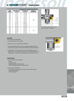
CHAMFER RINGS Chamfer Ring Position Range Drill Drill Body 3xD Drill Body 5xD Maximum Diameter L (min-max) L (min-max) Chamfer Size .394 .31-.63 .59-1.42 .413 .31-.71 .67-1.54 .433 .31-.75 .71-1.61 .453 .31-.83 .79-1.73 .472 .31-.87 .83-1.81 .492 .31-.94 .91-1.93 .06 .512 .31-.98 .94-2.01 .531 .31-1.06 1.02-2.13 .551 .35-1.14 1.10-2.24 .571 .35-1.22 1.18-2.36 .591 .35-1.18 1.14-2.36 The “L” dimension shown is for a .04” chamfer. .630 .35-1.30 1.26-2.56 For other sizes, adjust “L” accordingly. .699 .43-1.38 1.34-2.72 .709 .43-1.50 1.46-2.91 .08 .748 .43-1.65 1.61-3.15 .787 .43-1.77 1.73-3.35 User Guide Recommendation for better stability: • Use 3xD drill instead of 5xD, if possible. • Mount the ring as close as possible to the drill shank. • In order to get better chamfer insert life, it is suggested to apply coolant to the chamfer insert in addition to the through the drill coolant and/or external coolant.. • A wider difference “X” between the drill body and the replaceable point size is preferred (i.e., for .575” replaceable point select .551” drill body rather than .571”). A slightly larger “X” dimension can dramatically increase the chamfer insert life. Trouble Shooting • Bad chamfer surface finish (vibrations) Solutions: • Use a shorter drill. • Move the ring closer to the drill shank. • Reduce the cutting speed while cutting th chamfer. • Chips packed on the ring flutes: • Ensure that the ring is positioned as shown in the mounting instructions. • Adjust the cutting speed. • Use a pecking cycle. 683