Общий каталог Ingersoll 2011 - страница 312
Навигация
 Общий каталог Ingersoll 2016 - 2017
 Общий каталог Ingersoll 2014
 Каталог Ingersoll инструмент для нарезания резьбы
 Общий каталог Ingersoll 2013 - 2014
 Каталог Ingersoll новинки 2021
- 0003 Table of Contents
- 0006 End Mills
- 0064 Long Edge
- 0104 0Deg Face Mills
- 0160 Face Mills
- 0202 Slotters
- 0218 Form Mills
- 0236 Profile Mills
- 0302 Milling Tech
- 0384 Solid Carbide
- 0448 Solid Carbide Tech
- 0474 Holemaking & Thread Milling
- 0666 Holemaking & Thread Milling Tech
- 0720 Innofit Top On Toolholders
- 0738 HSK Toolholders
- 0774 CAT Toolholders
- 0796 BT Toolholders
- 0816 Adaptions Accessories
- 0872 Turning Inserts
- 1024 Turning Holders
- 1144 Turning Tech
- 1174 Threading Inserts
- 1242 Threading Holders
- 1256 Threading Tech
- 1268 T-Clamp
- 1344 T-Clamp Tech
- 1376 T-CAP
- 1388 T-CAP Tech
- 1394 Product_Index
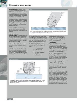
BALL NOSE “STURZ” MILLING Ball Nose Milling. Ball nose end milling Fig. 2 is a unique application that presents unique challenges. The nose inserts on a ball nose end mill are subjected to extreme abnormal and inconsistent work stresses. This is due, in part, to the wide variance in SFM and chip load from the radial to the axial end of the insert. In order to minimize the stresses generated by this condition, the spindle axis can be tilted to raise the center point of the tool out of the cut (Figure 2). This “sturz” milling greatly reduces the force variance on the insert and helps to equalize the chip load. To utilize this technique in optimizing your ball nose milling application, you must be able to tilt your machine spindle relative to the workpiece “Sturz” milling, or tilting the axis of the spindle to move the axial center of a ball nose end mill out of the cut, greatly reduces the cutting forces inflicted on the nose insert. Axial Chip Thickness Effective Diameter: When applying ball nose end mills, quite often the full diameter of the The effective cutting diameter can be found In order to achieve the best productivity cutter is not engaged in the work. Since ball in Chart A on pages M466-M467 by using the possible, be sure to consider the effective nose end mills cut to center, the speed in SFM nominal tool diameter at the top and the DOC cutting diameter when setting RPM for a is reduced to 0 as the centerline of the cutter is on the side. The SFM is calculated using the profiling ball nose application. reached (see Figure 1 below). resulting effective cutting diameter at DOC. Chip Thickness To determine the Axial Chip Thinning Factor The effective cutting diameter can also be Due to the spherical form presented to the (ACTF), first determine the effective cutting calculated by using the following formula: workpiece, axial chip thinning can affect chip diameter. Where: thickness the same way as a lead angle on a face mill. This can have an adverse effect on the As the DOC varies, so does the effective cuttingdiameter. Since SFM calculations are basedDt = 2 xR2 – (R – D)2 performance of a ball nose end mill. The ACTFmust be applied when calculating the desired on the diameter of the cutter engaged in the chip thickness and resulting feed rate. cut, they must be made at the effective cutting Dt = True cutting Diameter (in.) diameter, not the nominal diameter of the tool. R = Radius (in.) The ACTF is determined by the radius of the D = Depth of cut (in.) ball nose at a given DOC. Figure 2 illustrates the concept of axial chip thinning. Notice as the axial DOC increases, so does the axial chip Fig. 1: Effective Diameter thickness. To calculate axial chip thickness: ACTF = 1– 1– 2 x DOC 2 2.000" Ctr. Dia. Dia. Whenever the axial DOC is equal to or greater than the radius of the ball nose, the ACTF is .125"RadialDOC.125" .968"Dia.ActualDOC 1.000"Max.DOC equal to 1.Next, determine the RCTF by the chart on pagesM466-M467 or the formula. As Figure 3 shows, the RCTF is determined by the radius of the cutter at a given radial DOC. When determining CL the RCTF, use the effective diameter of the ball 242 0 500 nose rather than the cutter diameter. Radial SFM SFM SFM DOC is the same as the radial “step over.” The formula used to calculate axial chip thinning is In this example, the SFM is 500 at a 2.000” diameter. The effective cutting diameter is .968”, at whichpoint, the SFM is 242. The RPM must be increased to 1973 in order to achieve 500 SFM at the .968”effective cutting diameter.the same as that used for radial chip thinning.Ultimately, the purpose of determining thechip thinning factor is to optimize the feed rate. 314