Общий каталог Ingersoll 2011 - страница 311
Навигация
 Общий каталог Ingersoll 2016 - 2017
 Общий каталог Ingersoll 2014
 Каталог Ingersoll инструмент для нарезания резьбы
 Общий каталог Ingersoll 2013 - 2014
 Каталог Ingersoll новинки 2021
- 0003 Table of Contents
- 0006 End Mills
- 0064 Long Edge
- 0104 0Deg Face Mills
- 0160 Face Mills
- 0202 Slotters
- 0218 Form Mills
- 0236 Profile Mills
- 0302 Milling Tech
- 0384 Solid Carbide
- 0448 Solid Carbide Tech
- 0474 Holemaking & Thread Milling
- 0666 Holemaking & Thread Milling Tech
- 0720 Innofit Top On Toolholders
- 0738 HSK Toolholders
- 0774 CAT Toolholders
- 0796 BT Toolholders
- 0816 Adaptions Accessories
- 0872 Turning Inserts
- 1024 Turning Holders
- 1144 Turning Tech
- 1174 Threading Inserts
- 1242 Threading Holders
- 1256 Threading Tech
- 1268 T-Clamp
- 1344 T-Clamp Tech
- 1376 T-CAP
- 1388 T-CAP Tech
- 1394 Product_Index
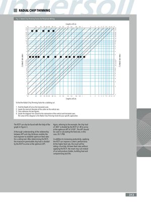
Cutter Diameter Cutter Diameter RADIAL CHIP THINNING Fig. 3: Radial Chip Thinning Factors for Peripheral Milling Depth of Cut .01 .02 .03 .04 .05 .06 .08 0.1 .15 0.2 0.3 0.4 0.6 0.8 1 2 3 4 5 6 7 8 10 12 15 30 30 25 25 .05 .06 .08 .1 .12 20 20 18 18 16 16 14 14 12 12 10 10 9 9 8 8 7 7 6 6 5 5 4 4 3 3 .14 .16 .18 .2 .25 .3 .4 .5 .6 .7 .8 .9 .95 1.0 2 2 1.8 1.8 1.6 1.6 1.4 1.4 1.2 1.2 1 1 .9 .9 .8 .8 .7 .7 .6 .6 .5 .5 .4 .4 .3 .3 .2 .2 .1 .1 .01 .02 .03 .04 .05 .06 .08 0.1 .15 0.2 0.3 0.4 0.6 0.8 1 2 3 4 5 6 78 10 12 15 Depth of Cut To find the Radial Chip Thinning Factor for a slabbing cut: 1. Find the Depth of Cut on the horizontal scale. 2. Locate the nominal diameter of the cutter on the vertical axis. 3. Cross-reference the two figures. 4. Locate the diagonal line closest to the intersection of the vertical and horizontal axes. The value of this diagonal is the Radial Chip Thinning Factor for your specific application. The RCTF can also be found with the help of the Again, referring to the example, the chip load graph in Figure 3. of .005” is divided by the RCTF of .48 to arrive at the optimum APT of .0105”. This APT should A thorough understanding of the relationship be used in calculating the feed rate, in this between APT and chip thickness enables the case, 20.1 IPM. tool engineer to establish optimum feed rates for a cutting tool. After determining the RCTF, In addition to increasing productivity, applying the maximum permissible chip load is divided the RCTF can improve a cutter’s performance. by the RCTF to arrive at the optimum APT. At the higher feed rate, the insert will be taking a true bite. At lower feed rates without applying the RCTF, the insert may rub instead of cut and produce chatter, building heat and compromising tool life. 313