Общий каталог Ingersoll 2011 - страница 313
Навигация
 Общий каталог Ingersoll 2016 - 2017
 Общий каталог Ingersoll 2014
 Каталог Ingersoll инструмент для нарезания резьбы
 Общий каталог Ingersoll 2013 - 2014
 Каталог Ingersoll новинки 2021
- 0003 Table of Contents
- 0006 End Mills
- 0064 Long Edge
- 0104 0Deg Face Mills
- 0160 Face Mills
- 0202 Slotters
- 0218 Form Mills
- 0236 Profile Mills
- 0302 Milling Tech
- 0384 Solid Carbide
- 0448 Solid Carbide Tech
- 0474 Holemaking & Thread Milling
- 0666 Holemaking & Thread Milling Tech
- 0720 Innofit Top On Toolholders
- 0738 HSK Toolholders
- 0774 CAT Toolholders
- 0796 BT Toolholders
- 0816 Adaptions Accessories
- 0872 Turning Inserts
- 1024 Turning Holders
- 1144 Turning Tech
- 1174 Threading Inserts
- 1242 Threading Holders
- 1256 Threading Tech
- 1268 T-Clamp
- 1344 T-Clamp Tech
- 1376 T-CAP
- 1388 T-CAP Tech
- 1394 Product_Index
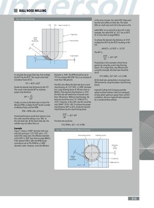
BALL NOSE MILLING Fig. 2: Axial Chip Thinning In the same manner, the radial DOC (step over) has the same effect on feed rate. The radial Step-Over (WOC) DOC on a ball nose end mill is the same as the radial WOC on an end mill or face mill. In this example, the radial DOC of .125” has an RCTF First Pass of .67 (see chart on page M463). Axial ChipThickness Second Pass To achieve the desired chip thickness of .010”, multiply the ACTF by the RCTF resulting in the FCF. .48 ACTF x .67 RCTF = .32 FCF The APT is: DOC Cusp Height .010” = .021” APT.32 Productivity in this example is three times greater by using the correct chip thinning factors. On a single flute, one-effective tool using this example, the feed rate should be set at: To calculate the proper feed rate, first multiply diameter is .968”, the RPM should be set atthe ACTF by the RCTF. This result is the Feed1973 to achieve 500 SFM. This is an increase of1973 RPM x .031” APT = 61.3 IPM Correction Factor (FCF): more than 100 percent. At this feed rate, productivity is increased over FCF = RCTF x ACTF 200 percent by using the proper chip thinningThe DOC also affects the feed rate due to axialfactors. Divide the desired chip thickness by the FCF. chip thinning. At .125” DOC, a 2.000” diameter This result is the desired APT to maintain has a chip thinning factor of .48 (see chart on Ingersoll Cutting Tool Company provides proper chip thickness: M463). If the desired chip thickness is .010”, speed and feed selectors which are designed APT = CTFCF the feed rate will need to be increased more to help obtain optimum speed, feed, and ACTthan 100 percent. Without chip thinning, themultipliers. Ask your Ingersoll sales engineerfeed rate would be set at 19.7 IPM (1973 xfor a complimentary selector. Finally, to arrive at the feed rate in Inches Per .010”). However, at this DOC, the ACT would be Minute (IPM), multiply the APT by the number only .0048” (.010 x .48). To achieve the proper of effective flutes and the RPM: chip thickness (APT or ACT), divide the desired chip thickness by the chip thinning factor. IPM = RPM x (No. of Flutes) Overall performance would also improve sincethe cutter would be taking a true “bite” at.010” = .021” APT.48 the new feed rate. At the lower feed rate, the The feed rate would be: carbide may rub rather than cut. 1973 RPM x .021 = 41.4 IPM Example Figure 1 shows a 2.000” diameter ball nose Fig. 3: Radial Chip Thinning at Effective Diameter end mill running at .125” DOC and a .125” radial DOC (step over). the effective diameter Second Revolution First Revolution at this DOC is .968” (see chart on page M463). If the desired SFM is 500, the RPM would normally be set at 955 RPM for a 2.000” diameter cutter. However, since the effective AdvancePer Tooth Radial ChipThickness Cutter Dia. Effective Dia. WOC 315 Step-Over (WOC)