Общий каталог Ingersoll 2011 - страница 308
Навигация
 Общий каталог Ingersoll 2016 - 2017
 Общий каталог Ingersoll 2014
 Каталог Ingersoll инструмент для нарезания резьбы
 Общий каталог Ingersoll 2013 - 2014
 Каталог Ingersoll новинки 2021
- 0003 Table of Contents
- 0006 End Mills
- 0064 Long Edge
- 0104 0Deg Face Mills
- 0160 Face Mills
- 0202 Slotters
- 0218 Form Mills
- 0236 Profile Mills
- 0302 Milling Tech
- 0384 Solid Carbide
- 0448 Solid Carbide Tech
- 0474 Holemaking & Thread Milling
- 0666 Holemaking & Thread Milling Tech
- 0720 Innofit Top On Toolholders
- 0738 HSK Toolholders
- 0774 CAT Toolholders
- 0796 BT Toolholders
- 0816 Adaptions Accessories
- 0872 Turning Inserts
- 1024 Turning Holders
- 1144 Turning Tech
- 1174 Threading Inserts
- 1242 Threading Holders
- 1256 Threading Tech
- 1268 T-Clamp
- 1344 T-Clamp Tech
- 1376 T-CAP
- 1388 T-CAP Tech
- 1394 Product_Index
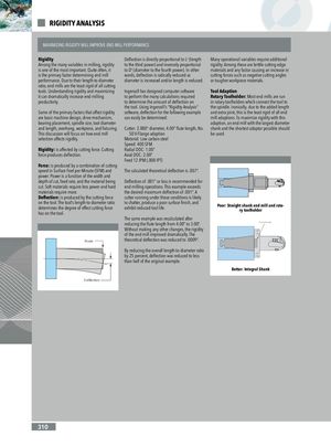
RIGIDITY ANALYSIS Centering Plug MAXIMIZING RIGIDITY WILL IMPROVE END MILL PERFORMANCE Rigidity Deflection is directly proportional to L3 (length Many operational variables require additional Among the many variables in milling, rigidity to the third power) and inversely proportional rigidity. Among these are brittle cutting edge is one of the most important. Quite often, it to D4 (diameter to the fourth power). In other materials and any factor causing an increase in is the primary factor deteCrmenitneirninggePnludgmill words, deflection is radically reduced as .125" Gap cutting forces such as negative cutting angles performance. Due to their length-to-diameter diameter is increased and/or length is reduced. or tougher workpiece ma.t1e2ri5aC"les.nGtaepring Plug ratio, end mills are the least rigid of all cutting tools. Understanding rigidity and maximizing Ingersoll has designed computer software Tool Adaption it can dramatically increase end milling to perform the many calculations required Rotary Toolholder: Most end mills are run productivity. to determine the amount of deflection on in rotary toolholders which connect the tool to the tool. Using Ingersoll’s “Rigidity Analysis” the spindle. Ironically, due to the added length Some of the primary factors that affect rigidity software, deflection for the following example and extra joint, this is the least rigid of all end are basic machine design, drive mechanism, can easily be determined: mill adaptions. To maximize rigidity with this bearing placement, spindle size, tool diameter adaption, an end mill with the largest diameter and length, overhang, workpiece, and fixturing. Cutter: 2.000” diameter, 4.00” flute length, No. shank and the shortest adaptor possible should This discussion will focus on how end mill 50 V-Flange adaption be used. selection affects rigidity. Material: Low carbon steel Speed: 400 SFM Rigidity: is affected by cutting force. Cutting Radial DOC: 1.00” force produces deflection. Axial DOC: 2.00” Feed 12 IPM (.008 IPT) Force: is produced by a combination of cutting speed in Surface Feet per Minute (SFM) and The calculated theoretical deflection is .007”. power. Power is a function of the width and Centeirng Pulg depth of cut, feed rate, and the material being Deflection of .001” or less is recommended for cut. Soft materials require less power and hard end milling operations. This example exceeds materials require more. the desired maximum deflection of .001”. A Deflection: is produced by the cutting force cutter running under these conditions is likely on the tool. The tool’s length-to-diameter ratio to chatter, produce a poor surface finish, anddetermines the degree of effect cutting forceexhibit reduced tool life.has on the tool.Poor: Straight shank end mill and rota-ry toolholder The same example was recalculated after reducing the flute length from 4.00” to 3.00”. Centeirng Pulg Without making any other changes, the rigidity of the end mill improved dramatically. The Force theoretical deflection was reduced to .0009”. Force By reducing the overall length-to-diameter ratio by 25 percent, deflection was reduced to less than half of the original example. Better: Integral Shank Deflection Deflection Force Deflection 310