Общий каталог Ingersoll 2011 - страница 307
Навигация
 Общий каталог Ingersoll 2016 - 2017
 Общий каталог Ingersoll 2014
 Каталог Ingersoll инструмент для нарезания резьбы
 Общий каталог Ingersoll 2013 - 2014
 Каталог Ingersoll новинки 2021
- 0003 Table of Contents
- 0006 End Mills
- 0064 Long Edge
- 0104 0Deg Face Mills
- 0160 Face Mills
- 0202 Slotters
- 0218 Form Mills
- 0236 Profile Mills
- 0302 Milling Tech
- 0384 Solid Carbide
- 0448 Solid Carbide Tech
- 0474 Holemaking & Thread Milling
- 0666 Holemaking & Thread Milling Tech
- 0720 Innofit Top On Toolholders
- 0738 HSK Toolholders
- 0774 CAT Toolholders
- 0796 BT Toolholders
- 0816 Adaptions Accessories
- 0872 Turning Inserts
- 1024 Turning Holders
- 1144 Turning Tech
- 1174 Threading Inserts
- 1242 Threading Holders
- 1256 Threading Tech
- 1268 T-Clamp
- 1344 T-Clamp Tech
- 1376 T-CAP
- 1388 T-CAP Tech
- 1394 Product_Index
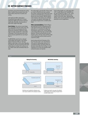
BETTER SURFACE FINISHES geometries and provide extremely free cutting The cutting edge is ground with a hook as well Finish milling depths are usually light (.003”- action. Excellent chip evacuation leaves the as a radius so that the axial rake is positive. .010”). Greater Advance Per Tooth (APT) can finish-milled surface free of scratches and This creates a shearing action which eases entry be used, sometimes as high as .125”. Finish scoring. into the cut and directs chips up and away so milling cutters should be less dense than they do not cause scratches. With this type of rough or semi-finish cutters, although high- Lead angle also affects cutting forces. insert, however, if the advance per revolution density cutters may be required for some high Increasing the lead angle from 0° lessens is too great, the elliptical cutting edges will production cast iron applications. radial force slightly and increases axial force not overlap enough to form a smooth surface significantly. Generally, chip evacuation is finish. easier with a higher lead angle. Other recommendations. Climb milling is Insert design. One common insert design generally best for finish milling because the has a wiping flat on the face of the insert. The cutter takes the thick part of the chip when it width of this flat must be greater than the enters the cut. In conventional milling, the advance per revolution to allow the cutting chip thickness starts at zero, causing rubbing edges to overlap. Spindle tilt is critical when or burnishing before the chip can reach its full using wipers. Due to the sharp ends on the thickness. Pressure and heat build up at the insert, excessive spindle tilt can cause dig-in finished surface. The thin section will then weld (Fig. 3). to the cutting edge and be carried around to scratch the surface. The MICRO MILL insert has four radiused cutting edges which project a very shallow Avoid cutting with the full diameter of the ellipse in the plane of the cut. The large tool. This also results in zero chip thickness elliptical radius aligns to the surface regardless at the point of cutting edge entry just as in of spindle tilt. This ensures that the ends of the conventional milling. Two-thirds of the tool cutting edge do not dig-in the surface as can diameter is best when finish milling. It is also occur when inserts with conventional flats are important to cut in the same direction when used. consecutive passes are required. Fig. 3 Wiping Flat Geometry MICRO MILL Geometry Proper Spindle Tilt Proper APT Wiping Flat Shallow Ellipse Excessive Spindle Tilt Excessive APT Dig-In Scallops Avoid too much spindle tilt, otherwise scrat- If advance per tooth is too great, the elliptical ches may be created on the workpiece surface. cutting edges will not overlap enough to form a smooth surface finish. 309