Общий каталог Yamawa 2021 - страница 625
Навигация
 Обший каталог Yamawa 2016 - 2017
 Краткое руководство Yamawa по каталогам
 Общий каталог Yamawa 2022 - 2023
 Каталоги Yamawa твердосплавные метчики для закаленной стали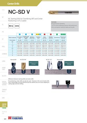
Intro NC-SD V
SP
NC Starting Drills for Chamfering (90°) and Center
Positioning (125°), Coated
FEATURES SL 90° type for hole chamfering.
HSS-Co COATING 125° for center positioning, improves drill performance.
HSSCo and special coating for stable and long life.
PO
| P1 | P2 | P3 | M1 M2 P7 | K1 | K2 | N1 | N2 N3 N4 | |
| Work-materials | Low carbon steel | Carbon and low alloy steel | Medium alloy steel | Stainless steel | Grey cast iron | Nodular cast iron | Aluminium | Aluminium die cast |
| Vc(m/min) | 25÷40 | 25÷32 | 15÷25 | 7÷12 | 20÷35 | 20÷35 | 60÷90 | 60÷90 |
| DC | fn(mm/rev) | fn(mm/rev) | fn(mm/rev) | fn(mm/rev) | fn(mm/rev) | fn(mm/rev) | fn(mm/rev) | fn(mm/rev) |
| 1 | 0.03÷0.06 | 0.03÷0.06 | 0.03÷0.06 | 0.03÷0.06 | 0.03÷0.06 | 0.03÷0.06 | 0.03÷0.06 | 0.03÷0.06 |
| 1.5 | 0.05÷0.10 | 0.05÷0.10 | 0.05÷0.10 | 0.05÷0.10 | 0.05÷0.10 | 0.05÷0.10 | 0.05÷0.10 | 0.05÷0.10 |
| 2 | 0.08÷0.15 | 0.08÷0.15 | 0.08÷0.15 | 0.08÷0.15 | 0.08÷0.15 | 0.08÷0.15 | 0.08÷0.15 | 0.08÷0.15 |
| 2.5 | 0.10÷0.18 | 0.10÷0.18 | 0.10÷0.18 | 0.10÷0.18 | 0.10÷0.18 | 0.10÷0.18 | 0.10÷0.18 | 0.10÷0.18 |
| 3 | 0.15÷0.20 | 0.15÷0.20 | 0.15÷0.20 | 0.15÷0.20 | 0.15÷0.20 | 0.15÷0.20 | 0.15÷0.20 | 0.15÷0.20 |
| 4 | 0.15÷0.25 | 0.15÷0.25 | 0.15÷0.25 | 0.15÷0.25 | 0.15÷0.25 | 0.15÷0.25 | 0.15÷0.25 | 0.15÷0.25 |
| 5 | 0.15÷0.30 | 0.15÷0.30 | 0.15÷0.30 | 0.15÷0.30 | 0.15÷0.30 | 0.15÷0.30 | 0.15÷0.30 | 0.15÷0.30 |
| 6 | 0.20÷0.30 | 0.20÷0.30 | 0.20÷0.30 | 0.20÷0.30 | 0.20÷0.30 | 0.20÷0.30 | 0.20÷0.30 | 0.20÷0.30 |
LONG
HAND
TAPS
Normal drill
NC-SD V 90°
NC-SD 125° Normal drill Drilling process is Drilling process is fi nished. fi nished.
EG (STI)
Diff erence between starting drills and center drills SPECIAL For positioning, center drills can also be used. However in the case of center drill, THREADS, since cutting edge of normal drill fi rst hits the material, this can cause chipping on GAUGES cutting edge and slant drilling.