Общий каталог Widia 2017 - страница 693
Навигация
 Каталог Widia токарный инструмент 2017
 Каталог Widia трохоидальное фрезерование
 Каталог Widia техническое руководство по разверткам
 Каталог Widia фрезы со сменными пластинами 2016
 Каталог Widia достижения 2020
- Table of Contents
- Turning
- Turning • ISO Inserts
- Turning • Tools for External Turning and Internal Boring
- Turning • Tools for External Turning and Internal Boring
- Turning • Tools for Small Hole Boring
- com E1Turning • Grooving and Cut-Off
- Turning • Threading
- Indexable Milling
- Indexable Milling • Face Mills
- Indexable Milling • Chamfer Mills
- Indexable Milling • 90° Shoulder Mills
- Indexable Milling • Helical Mills
- Indexable Milling • Slotting Mills
- Indexable Milling • Copy Mills
- Solid End Milling
- Solid End Milling • High-Performance Solid Carbide End Mills
- Solid End Milling • General Purpose Solid Carbide End Mills
- Solid End Milling • High-Performance High-Speed Steel (HSS-E/PM)
- Solid End Milling • Burs
- Holemaking
- Holemaking • High-Performance Solid Carbide Drills
- Holemaking • Modular Drills
- Holemaking • Indexable Drills
- Holemaking • Modular Drills
- Holemaking • Indexable Drills
- Holemaking • Hole Finishing
- Tapping
- Tapping Portfolio
- Index by Order Number
- Index by Catalogue Number
- Global Contacts
- Informational Icons Guide
- Material Overview • DIN
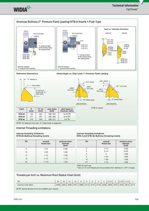
American Buttress (7° Pressure Flank Leading) NTB-A Inserts • Push Type
Insert vs. Toolholder Orientation chuck chuck
anti-clockwise anti-clockwise external internal
rotation rotation 7º NTB-2RA feed
NTB-3RA NTB-4RA NTB-2LA seating 7° pressure fl ank surface NTB-3LA seating of the thread being in bar
| 7º | NTB-4LA | surface | |||
| the leading fl ank | |||||
| in toolholder | |||||
| feed | insert | ||||
| insert | notch |
| NTB-2RA | 7° pressure fl ank | notch | |
| NTB-3RA | of the thread being | ||
| NTB-4RA | the leading fl ank | NTB-2LA |
NTB-3LA NTB-4LA external buttress internal buttress 7° pressure fl ank leading 7° pressure fl ank leading
Reference Dimensions Infeed Angle vs. Chip Load: 7° Pressure Flank Leading
“A” reference .010" infeed .010" infeed nose radius .007" chip load .0052" .0039" chip load chip load .0012" D maximum chip load depth with “A” style insert
15º infeed angle 0º infeed angle feed direction feed direction NTB-A insert
| insert | D | “A” ref. | nose radius | pitch based on | |||
| (inch) | (inch) | (inch) | maximum radius | ||||
| NTB-2A | .133 | .024 | .002–.004 | 16–20 TPI | |||
| NTB-3A | .171 | .031 | .005–.008 | 8–16 TPI | |||
| NTB-4A | .218 | .049 | .008–.012 | 4–6 TPI | |||
| NOTE: For balanced chip load, 15° infeed angle is suggested. | |||||||
| Internal Threading Limitations | |||||||
| internal threading limitations | internal threading limitations | ||||||
| NTB-2A Buttress threading inserts | NTB-3 and NTB-4A Buttress threading inserts |
| TPI | nominal | minimum minor | TPI | nominal | minimum minor | ||
| thread size | diameter | thread size | diameter |
(inch) (inch)
| TPI | nominal thread size | minimum minor diameter (inch) | TPI | nominal thread size | minimum minor diameter (inch) |
| 8 | 1-3/4 | 1.600 | 4 | 2-1/2 | 2.200 |
| 10 12 | 1-5/8 1-1/2 | 1.505 1.400 | 5 6 8 | 2-1/4 2 1-3/4 | 2.010 1.800 1.600 |
| 16 | 1-1/4 | 1.175 | 10 | 1-5/8 | 1.505 |
| 20 | 1-1/16 | 1.002 | 12 | 1-1/2 | 1.400 |
Threads per Inch vs. Maximum Root Radius Chart (Inch)
TPI 20 16 12 10 8 6 5 4 3 2-1/2 2 1-1/2 1-1/4 1
maximum root radius .0036 .0045 .0059 .0071 .0089 .0119 .0143 .0179 .0238 .0268 .0375 .0476 .0572 .0714 NOTE: Special Buttress forms are available upon request.