Общий каталог Widia 2017 - страница 594
Навигация
 Каталог Widia токарный инструмент 2017
 Каталог Widia трохоидальное фрезерование
 Каталог Widia техническое руководство по разверткам
 Каталог Widia фрезы со сменными пластинами 2016
 Каталог Widia достижения 2020
- Table of Contents
- Turning
- Turning • ISO Inserts
- Turning • Tools for External Turning and Internal Boring
- Turning • Tools for External Turning and Internal Boring
- Turning • Tools for Small Hole Boring
- com E1Turning • Grooving and Cut-Off
- Turning • Threading
- Indexable Milling
- Indexable Milling • Face Mills
- Indexable Milling • Chamfer Mills
- Indexable Milling • 90° Shoulder Mills
- Indexable Milling • Helical Mills
- Indexable Milling • Slotting Mills
- Indexable Milling • Copy Mills
- Solid End Milling
- Solid End Milling • High-Performance Solid Carbide End Mills
- Solid End Milling • General Purpose Solid Carbide End Mills
- Solid End Milling • High-Performance High-Speed Steel (HSS-E/PM)
- Solid End Milling • Burs
- Holemaking
- Holemaking • High-Performance Solid Carbide Drills
- Holemaking • Modular Drills
- Holemaking • Indexable Drills
- Holemaking • Modular Drills
- Holemaking • Indexable Drills
- Holemaking • Hole Finishing
- Tapping
- Tapping Portfolio
- Index by Order Number
- Index by Catalogue Number
- Global Contacts
- Informational Icons Guide
- Material Overview • DIN
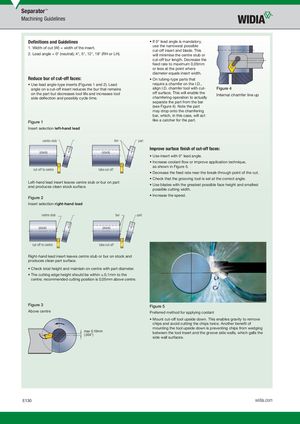
Defi nitions and Guidelines
1. Width of cut (W) = width of the insert. 2. Lead angle = 0° (neutral); 4°, 5°, 12°, 18° (RH or LH).
Reduce bur of cut-off faces:
- Use lead angle-type inserts (Figures 1 and 2). Lead angle on a cut-off insert reduces the bur that remains on the part but decreases tool life and increases tool side defl ection and possibly cycle time.
Figure 1 Insert selection left-hand lead
centre stub bur
(stock) (stock)
cut-off to centre tube cut-off
Left-hand lead insert leaves centre stub or bur on part and produces clean stock surface.
Figure 2 Insert selection right-hand lead
centre stub bur
(stock) (stock)
part
part
- If 0° lead angle is mandatory, use the narrowest possible cut-off insert and blade. This will minimise the centre stub or cut-off bur length. Decrease the feed rate to maximum 0,05mm or less at the point where diameter equals insert width.
- On tubing-type parts that require a chamfer on the I.D., align I.D. chamfer tool with cut- Figure 4 off surface. This will enable the
Internal chamfer line up chamfering operation to actually separate the part from the bar (see Figure 4). Note the part may drop onto the chamfering bar, which, in this case, will act like a catcher for the part.
Improve surface fi nish of cut-off faces:
- Use insert with 0° lead angle.
- Increase coolant fl ow or improve application technique, as shown in Figure 5.
- Decrease the feed rate near the break-through point of the cut.
- Check that the grooving tool is set at the correct angle.
- Use blades with the greatest possible face height and smallest possible cutting width.
- Increase the speed.
cut-off to centre tube cut-off
Right-hand lead insert leaves centre stub or bur on stock and produces clean part surface.
- Check total height and maintain on centre with part diameter.
- The cutting edge height should be within ±.0,1mm to the centre; recommended cutting position is 0,05mm above centre.
Figure 3 Figure 5 Above centre Preferred method for applying coolant
- Mount cut-off tool upside down. This enables gravity to remove chips and avoid cutting the chips twice. Another benefi t of mounting the tool upside down is preventing chips from wedging
max 0,10mm between the tool insert and the groove side walls, which galls the (.004") side wall surfaces.