Общий каталог Widia 2017 - страница 457
Навигация
 Каталог Widia токарный инструмент 2017
 Каталог Widia трохоидальное фрезерование
 Каталог Widia техническое руководство по разверткам
 Каталог Widia фрезы со сменными пластинами 2016
 Каталог Widia достижения 2020
- Table of Contents
- Turning
- Turning • ISO Inserts
- Turning • Tools for External Turning and Internal Boring
- Turning • Tools for External Turning and Internal Boring
- Turning • Tools for Small Hole Boring
- com E1Turning • Grooving and Cut-Off
- Turning • Threading
- Indexable Milling
- Indexable Milling • Face Mills
- Indexable Milling • Chamfer Mills
- Indexable Milling • 90° Shoulder Mills
- Indexable Milling • Helical Mills
- Indexable Milling • Slotting Mills
- Indexable Milling • Copy Mills
- Solid End Milling
- Solid End Milling • High-Performance Solid Carbide End Mills
- Solid End Milling • General Purpose Solid Carbide End Mills
- Solid End Milling • High-Performance High-Speed Steel (HSS-E/PM)
- Solid End Milling • Burs
- Holemaking
- Holemaking • High-Performance Solid Carbide Drills
- Holemaking • Modular Drills
- Holemaking • Indexable Drills
- Holemaking • Modular Drills
- Holemaking • Indexable Drills
- Holemaking • Hole Finishing
- Tapping
- Tapping Portfolio
- Index by Order Number
- Index by Catalogue Number
- Global Contacts
- Informational Icons Guide
- Material Overview • DIN
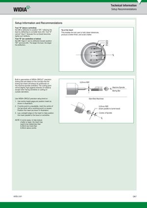
Setup Information and Recommendations
Tool “D” (above centreline) Set ØB is defl ected to position “DF,” relieving the Tip of the Insert load by defl ecting to a smaller bore, ØA. Tool “D” This enables the end user to hold closer tolerances, cannot “dig in” because the cut (load) becomes produce a better fi nish, and avoid chatter. lighter as it defl ects. Tool “E” (on centreline or below) Set ØB “digs in” and is defl ected toward position ØA “EF” and bore ØC. The larger the load, the larger ØB the defl ection. ØC D DF E EF
Built-in geometries of WIDIA-CIRCLE™ precision boring bars are based on the concept that the 0,25mm REF. boring bar shank will always be positioned on the machine spindle centreline. The cutting point will be slightly high (against direction of rotation) Machine Spindle except when facing centreline or cutting on Boring Bar outside diameters.
Use WIDIA-CIRCLE precision setup level or: Slant Bed Machines 1. Use centre height gage and position insert as shown in illustration. 2. If centre point is unavailable, mark the centre of 0,25mm REF. the bar stock with a centring punch or square. (insert parallel to turret travel) Position the insert as shown in illustration. 3. Lay a straight edge on the insert to help position Centre of Spindle the insert parallel to the travel or centreline.
NOTE: In some cases, to help reduce chatter or taper, the insert may need to be rotated less than 0,25mm but more than 0,05mm above centre.