Общий каталог Widia 2017 - страница 1787
Навигация
 Каталог Widia токарный инструмент 2017
 Каталог Widia трохоидальное фрезерование
 Каталог Widia техническое руководство по разверткам
 Каталог Widia фрезы со сменными пластинами 2016
 Каталог Widia достижения 2020
- Table of Contents
- Turning
- Turning • ISO Inserts
- Turning • Tools for External Turning and Internal Boring
- Turning • Tools for External Turning and Internal Boring
- Turning • Tools for Small Hole Boring
- com E1Turning • Grooving and Cut-Off
- Turning • Threading
- Indexable Milling
- Indexable Milling • Face Mills
- Indexable Milling • Chamfer Mills
- Indexable Milling • 90° Shoulder Mills
- Indexable Milling • Helical Mills
- Indexable Milling • Slotting Mills
- Indexable Milling • Copy Mills
- Solid End Milling
- Solid End Milling • High-Performance Solid Carbide End Mills
- Solid End Milling • General Purpose Solid Carbide End Mills
- Solid End Milling • High-Performance High-Speed Steel (HSS-E/PM)
- Solid End Milling • Burs
- Holemaking
- Holemaking • High-Performance Solid Carbide Drills
- Holemaking • Modular Drills
- Holemaking • Indexable Drills
- Holemaking • Modular Drills
- Holemaking • Indexable Drills
- Holemaking • Hole Finishing
- Tapping
- Tapping Portfolio
- Index by Order Number
- Index by Catalogue Number
- Global Contacts
- Informational Icons Guide
- Material Overview • DIN
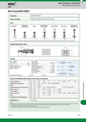
Drill Thread Mill GTM31
Preparation Drilling of thread hole
Process Principle Drilling, countersinking, thread milling (climb milling)
Cycle
Drilling and Run-in loop for Returning to
Positioning Raise Thread milling Run-out loop
countersinking thread milling positioning level
Required Specification Values
Example
| Size — M10-6H | Tool — GTM31 | Vc • 1000 | ||
| Thread diameter D .........................................10mm | Catalogue number ................................................GTM315005 | N = | S = 9709 | |
| d1 • / | ||||
| Pitch .............................................................1,5mm | Number of teeth Z .................................................................. 2 | |||
| Core hole diameter D1 ..................................8,5mm | Tool diameter d1 ..........................................................8,2mm* | |||
| 2427 (drilling, | ||||
| Material — Grey cast iron | Tool radius compensation k1 ..................................... 0,1mm** | vs = | fb • n F = | |
| countersinking) | ||||
| Grade — WU12PV | Tool radius to be programmed2 ...................................4mm*** | |||
| Countersink depth ls .................................................19,11mm | 1942 | |||
| Cutting speed vc .....................................................250 m/min | vf = | fz • Z • n F = | ||
| (contour) | ||||
| Feed (countersinking) fs ..........................................0,25 mm/U | ||||
| Feed (milling) fz ..................................................0,1 mm/tooth | vf contour • (D-d1) F = 350 | |||
| vf = | ||||
| D | (centre point) |
| *(measured on the cutting part) | **(0.01 x D) | ***(1/2 d1 - k) |
| Program to DIN 66025 (climb milling, on the contour, incremental) |
| Positioning the tool | N 10 | G 54 | G 90 | G 00 | X… | Y… | Z 2 | S 9709 | T01 2 | M03 |
| Drilling and countersinking | N 20 | G 91 | G 01 | Z-21.110 | F 2427 (drill, countersink) |
| Positioning the tool | N 10 | G 54 | G 90 | G 00 | X… | Y… | Z 2 | S 9709 | T012 | M03 |
| Drilling and countersinking | N 20 | G 91 | G 01 | Z-21.110 | F 2427 | (drill, count | ersink) | |||
| Raise | N 30 | G 01 | Z 0.500 | |||||||
| Moving sideways to the starting point | N 40 | G 41 | Y-4.250 | F 971 | (milling, 1/ | 2 contour) | [F 175]3 | (1/2 centre | point) | |
| Run-in loop in arc | N 50 | G 03 | X 0 | Y 9.250 | Z 0.750 | I 0 | J 4.625 | |||
| Thread milling | N 60 | G 03 | X 0 | Y 0 | Z 1.500 | I 0 | J -5.000 | |||
| Run-out loop in arc | N 70 | G 03 | X 0 | Y-9.250 | Z 0.750 | I 0 | J- 4.625 | F1942 | [F 350]3 | (centre point) |
| Exit | N 80 | G 00 | G 40 | X 0 | Y 4.250 | |||||
| Retracting tool topositioning level | N 90 | G 90 | Z 2 |
1 The cutter radius measured over the tooth crests of the threaded part must be reduced by the amount of the cutter radius compensation. This is necessary to achieve a depth of cut to the middle of the 6H/ISO2 nut tolerance. Please note, however, that this also depends on the radial deflection of the tool (tensile strength of the material, projecting length of the tool). 2 The cutter radius to be programmed is normally included in the tool memory. 3 The feed values in brackets must be used for controllers, which do not calculate the centre point feed themselves.