Каталог Widia инструментальная оснастка - страница 1106
Навигация
 Каталог Widia достижения 2021
 Брошюра Widia решения для аэрокосмической промышленности
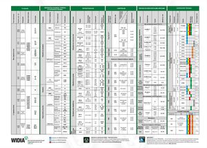 Брошюра Widia техническое руководство
 Каталог Widia токарный инструмент 2020
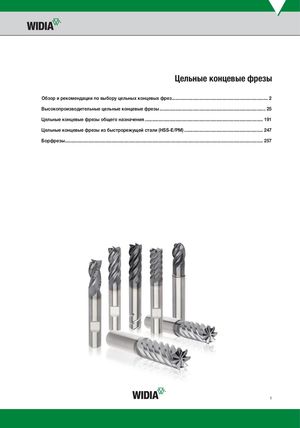 Каталог Widia цельные концевые фрезы
 Каталог Widia техническое руководство по разверткам
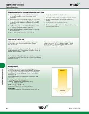
Technical Information Tunable Boring Bars General Guidelines for Boring with Extended Reach Bars 1. Select the largest boring bar diameter possible. Larger diameter bars 6. Make sure the insert is in the correct center position. are stiffer and more stable. Remember to leave enough space for chip evacuation. 7. By choosing a small corner radius you can reduce forces on the workpiece. 2. While larger diameters are more stable, the diameter may also be too large, 8. Use cutting heads with a negative back-rake angle that is as small preventing proper chip evacuation, affecting surface finish, or damaging as possible. the bar. Ensure the bar diameter is not so large that it will interfere with 9. Using inserts with a positive chip former is preferred. chip evacuation. 10. Change inserts when any flank wear is detected because radial back forces 3. Keep the overhang length of the tunable boring bar as short as possible. will increase in proportion to wear. For Tunable Boring Bars, select the shortest bar possible. 4. Balance machining parameters to prevent the occurrence of uncontrolled vibrations and resonance. 5. The tool setting angle should be as close as possible to 90°. Selecting the Correct Bar WIDIA™ offers TTS Boring Bars with KM™ back-ends or straight shanks, Please note that only standard pretuned straight shank tunable bars are KM front-ends, or bolt-on head connections, and they are available in pretuned at the factory for 10:1 L:D. If the straight shank bar is mounted either steel or carbide. with less than 10:1 L:D, it may be necessary to retune the bar. This is discussed in more detail in the “Tuning the Bar” section. To find the appropriate boring bar, first consider that the length-to-diameter ratio (L:D) should always be kept as small as possible. The smaller the L:D ratio, the greater the stiffness and stability of the bar. The L:D ratios of Tunable Boring Bars are fixed, where straight shank tunable bar L:D ratios are not. When using straight shank bars, the overhang length should be kept as small as possible. Holding Method The holding method is as critical to performance as selecting and tuning the boring bar. The connection between the boring bar and the machine should Most Stable be as rigid as possible. Rigid connections enable the tuner mass to function more effectively. The minimum holding length of the bar should be 2.5x the diameter of the bar. Various connection methods are shown below and listed from most stable to least stable: Face and Taper Contact with Interference Fit Example: KM Tunable Boring Bar clamped with short overhang KM clamping unit on turret Split Sleeve/Full Cylindrical Contact Example: Straight Shank Tunable Boring Bar with split sleeve Screw Clamping Example: Straight Shank Tunable Boring Bar with screw clamping on bar flat Least Stable K70 WWW.WIDIA.COM Technical Information