Каталог Widia инструментальная оснастка - страница 1073
Навигация
 Каталог Widia достижения 2021
 Брошюра Widia решения для аэрокосмической промышленности
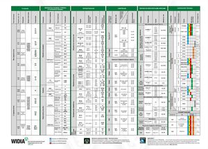 Брошюра Widia техническое руководство
 Каталог Widia токарный инструмент 2020
 Каталог Widia цельные концевые фрезы
 Каталог Widia техническое руководство по разверткам
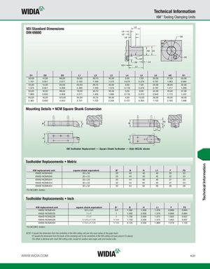
Technical Information KM™ Tooling Clamping Units VDI Standard Dimensions DIN 69880 D1 D2 D3 L1 L2 L3 L4 L5 L6 H2 R1 30,00 14,00 68,00 55,00 29,70 40,00 2,00 7,00 20,00 27,00 25,00 1.181 0.551 2.677 2.165 1.169 1.575 0.079 0.276 0.787 1.063 0.984 40,00 14,00 83,00 63,00 29,70 40,00 3,00 7,00 20,00 36,00 32,00 1.575 0.551 3.268 2.480 1.169 1.575 0.118 0.276 0.787 1.417 1.260 50,00 16,00 98,00 78,00 35,70 48,00 3,00 8,00 24,00 45,00 37,00 1.969 0.630 3.858 3.071 1.406 1.890 0.118 0.315 0.945 1.772 1.457 60,00 16,00 123,00 94,00 43,70 56,00 4,00 10,00 28,00 55,00 48,00 2.362 0.630 4.843 3.701 1.720 2.205 0.157 0.394 1.102 2.165 1.890 Mounting Details • NCM Square Shank Conversion KM Toolholder Replacement — Square Shank Toolholder — Style MCLNL shown Toolholder Replacements • Metric KM replacement unit square shank equivalent B* B H L1 F F2 KM32-NCM4040 20 x 20 20 40 40 45 22 23 KM32-NCM5040 25 x 25 25 40 50 45 22 23 KM40-NCM5044 25 x 25 25 44 50 40 27 23 KM40-NCM6444 32 x 32 32 44 64 40 27 23 KM50-NCM6454 32 x 32 32 54 64 50 35 28 *For MCLNR/L holders. Toolholder Replacements • Inch KM replacement unit square shank equivalent B* B H L1 F F2 KM32-NCM2425 3/4 x 3/4 3/4 1.562 1.500 1.378 0.866 0.884 KM32-NCM3225 1x1 1 1.562 2.000 1.378 0.866 0.884 KM40-NCM3228 1x1 1 1.750 2.000 1.575 1.063 0.937 KM40-NCM4028 1-1/4 x 1-1/4 1-1/4 1.750 2.500 1.575 1.063 0.937 KM50-NCM4034 1-1/4 x 1-1/4 1-1/4 2.125 2.500 1.969 1.378 1.122 *For MCLNR/L holders. NOTE: F equals the dimension from the centerline of the KM cutting unit over the nose radius of the gage insert. F2 equals the dimension from the back of the clamping unit to the centerline of the KM cutting unit (see column F2 above). The offset is identical with most KM cutting units, except for positive lead angle units and neutral units. WWW.WIDIA.COM K37 Technical Information