Каталог Widia инструментальная оснастка - страница 1060
Навигация
 Каталог Widia достижения 2021
 Брошюра Widia решения для аэрокосмической промышленности
 Брошюра Widia техническое руководство
 Каталог Widia токарный инструмент 2020
 Каталог Widia цельные концевые фрезы
 Каталог Widia техническое руководство по разверткам
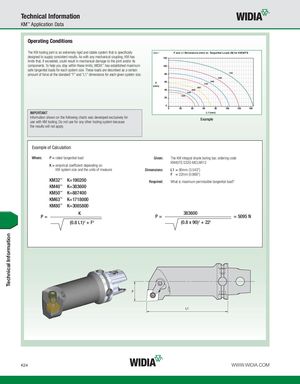
Technical Information KM™ Application Data Operating Conditions The KM tooling joint is an extremely rigid and stable system that is specifically Chart 1 F and L1 Dimensions (mm) vs. Tangential Loads (N) for KM32TS designed to supply consistent results. As with any mechanical coupling, KM has 120 limits that, if exceeded, could result in mechanical damage to the joint and/or its components. To help you stay within these limits, WIDIA™ has established maximum 100 safe tangential loads for each system size. These loads are described as a certain amount of force at the standard “F” and “L1” dimensions for each given system size. 80 1700 2000 F 60 24002700 (mm) 3400 40 4000 4700 5400 20 0 0 20 40 60 80 100 120 140 IMPORTANT L1 (mm) Information shown on the following charts was developed exclusively foruse with KM tooling. Do not use for any other tooling system because Example the results will not apply. Example of Calculation: Where: P = rated tangential load Given: The KM integral shank boring bar, ordering code KM40TS S32G-MCLNR12 K = empirical coefficient depending on KM system size and the units of measure Dimensions: L1 = 90mm (3.543") F = 22mm (0.866") KM32™ K=190200 Required: What is maximum permissible tangential load? KM40™ K=383600 KM50™ K=887400 KM63™ K=1718000 KM80™ K=3085800 KP= 383600P= = 5095 N (0.8 L1)2 + F2 (0.8 x 90)2 + 222 K24 WWW.WIDIA.COM Technical Information