Каталог Tungaloy глубокое сверление 1 - страница 3
Навигация
 Брошюра Tungaloy новая продукция
 Каталог Tungaloy инструмент для автоматов швейцарского типа
 Каталог Tungaloy глубокое сверление 2
 Общий каталог Tungaloy 2020 - 2021
 Каталог Tungaloy зубофрезерование
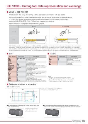
140° øDcm7 ød øDsh6 140° DCm7 IC DCONMSh6 ISO 13399 - Cutting tool data representation and exchange ■ What is ISO 13399? This Indexable BTA Deep Hole Drilling catalog is created in compliance with ISO 13399. ISO 13399 defines cutting tool data representation and exchange, allowing the accurate exchange of tooling data among computer aided applications that support and adhere to the standard, including CAD, CAM, CAE, PDM, PLM and tool management systems. Shown below are examples of the ISO 13399 symbols. Before ISO 13399 rε S RE S Insert øD D1 R L Drill LU(effective flute length) Re(effective flute length) LCF R OAL L ISO 13399 standardizes not only the format of 2D and 3D CAD data but also the tool dimension symbols (properties) and reference position information. This allows the tool information to be read and combined into NC programs and CAM software, regardless of any tool maker's data. In addition to the General Catalog (paper catalog), we are also updating the symbols in the e-catalog (electronic catalog on our website) to the properties conforming to ISO 13399. The e-catalog also provides 2D and 3D CAD data in accordance with ISO 13399 standard. ■ Drill ■ Insert New symbol Old symbol Description New symbol Old symbol Description BD øD1, øD2, øD3 Body external diameter IC ød Inscribed circle diameter CICT z Number of inserts INSL B Insert length CND - Oil hole diameter LE A Effective cutting edge length CNT - Oil hole plug size RE r Corner radius CRKS S Mounting screw size S T Thickness DC øDc Machining diameter W1 - Insert width DCONMS øDs Mounting part diameter on the machine DCONWS øD, ød2 Mounting part diameter on the workpiece DCSFMS øD Connecting part diameter KAPR κ Cutting edge angle LCF ℓ Flute length LF Lf Standard length (from the drill shoulder) LPR - Parting length (from flange to tip) LS ℓs Shank length LU ℓ Machinable depthNOFzNumber of flutesOALLOverall length (from tip)Note:- Symbols unspecified in ISO 13399 standardand Tungaloy’s original symbols are not included. PL PL Distance from drill tip to shoulder - The symbols still under discussion are included. ZEFP Z eff Number of effective cutting edges on periphery Please note any change or addition may occur. ■ CAD data provided in e-catalog ● 2D data (DXF format file) Includes actual cutting edge curve (CUT layer) and body cross section (NOCUT layer). ● 3D data Light type (STP format file): Can be used to check tool ● 3D data Detail type (STP format file): Can be used to create a new tool path and interference. layout chart. (Can be combined with any insert model on a CAD software.) A rotating body model of an actual cutting edge curve and a body cross section. Tungaloy 003