Каталог TooTool техническая информация 2 - страница 148
Навигация
 Каталог TooTool техническая информация 1
 Общий каталог TooTool
 Каталог TooTool монолитные фрезы
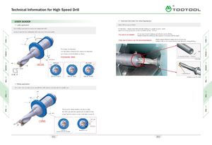
Technical Information for High Speed Drill A\ USER GUIDER » Technical Information for Lathe Applications »Lathe application Initial drill set up and check •On a milling machine the sleeve can change the drill's On first hole - please retract the drill after drilling to a depth of 3mm - 6mm and check it has produced a small core within 0.2mm - 0.7mm -nominal diameter by shifting the drill's axis out of the tool spindle. If a core is not created: —It can cause insert breakage and vibration when drilling.—Please reverse the drill body 180 degrees in tool post and try again. 90> D+0.4mi If the size of core is over the recommendations: —Please adjust offsets to bring core to correct size.—Failure to do so can cause overload and vibration during drilling. To enlarge the diameter, turn the sleeve clockwise 8t to reduce the diameter, 0d y turn sleeve counterclockwise as shown.Dd rill diameter: 30mm /(c ore d ia: 0.2mm - 0.7mm) D-0.2mm f. | MILLINGl Initial set up of U-Drill »Milling application •On a lathe, the eccentric sleeve can shift the drill's axis to coincide with the spindle axis. 0.0 90’ The eccentric sleeve enables the user to align the drill's axis with the spindle axis to within 0.2mm I +0.2 range (turn the sleeve counter clock wise to raise it). Tool's axis ,•1*0 | LATHE | lunetaxis Nominal d +0.2 651 652