Общий каталог Sumitomo 2019 - 2020 - страница 474
Навигация
 Каталог Sumitomo запасные части
 Каталог Sumitomo сплавы и режимы
 Техническая информация Sumitomo
 Каталог Sumitomo пластины с алмазными вставками Sumidia
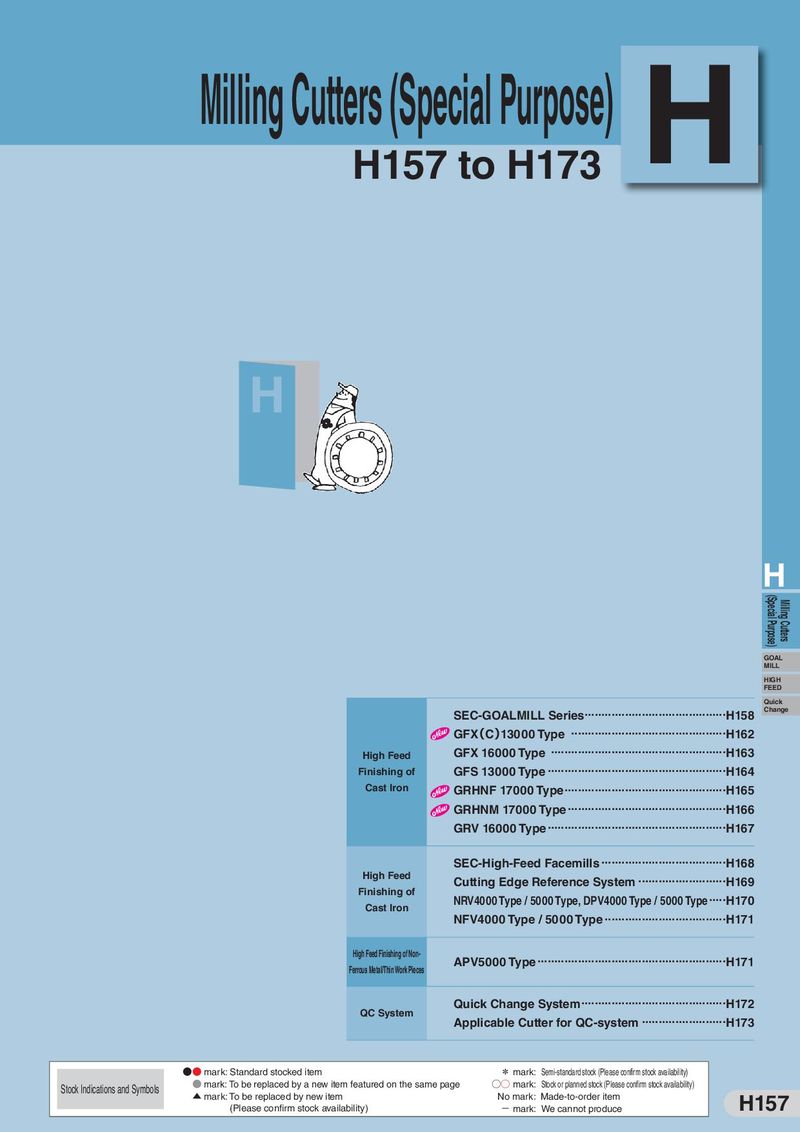 Каталог Sumitomo специальные торцевые фрезы
 Общий каталог Sumitomo 2018 - 2019
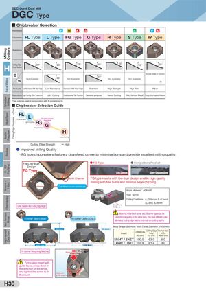
Milling CuttersFace MillingShoulde rMillingHigh FeedMulti-PurposeRadiusR / 3DProfilingGroove /T-SlotChamferingNon-ferrousMetalHigh-speedCast Iron GGooooddCuttingCEutdtignge ESdhgaerSphnarepsnsess Coating Hardness Flank wear Flank Wear Width SEC●-SCuhomosieDautoaoll Mto silulit your application from a comprehensive lineup DGC Type Cutter Diameter: ø40mm to ø250mm Cutter Diameter No. of Teeth: 3 to 10 Cutter Diameter: ø50mm to ø250mmCutter DiameterNo. of Teeth: 4 to 14 50mm 250mmCutter Diameter518 40mm 63mmCutter Diameter34 Cutting Edges Cutting Edges Cutting Edges Cutting Edges Mounting: Metric/Inch Mounting: Metric/Inch / ■ ChipbAtrtaechmaenkt: Meetrric/InSchelection Attachment: Metric/Inch Attachment: Metric/Imperial Attachment: Metric Work Material P M K S N P K Chipbreaker FL Type L Type FG Type G Type H Type S Type W Type Appearance DGC 13000R(S) DGCM 13000R(S) DGCF 13000R(S) DGC 13000EW Standard Pitch Fine pitch Standard PitchCutting Edge30°30° Fine Pitch25° 25° Ex2tr5a F°ine Pitch 30° Endmill Type25° H Cross Section ● High Reliability 8s1tEr6emspslocNyootsnAvtSarioulalbplteeercZhXnoCloogayti.nIgm30,p°aromvueNldtoit-rAluavanyiloeabruleetdpPreVcDisicoonartei2nd3g°ucgerasdNteoot,oAavlanliiladfebleCvVarDiactiNoooant At,ivnaiglabgleradDeouwblei-Stihdede, 2nCho(*r)anenrs ced coating strength provide achieving highly reliable tool life. FeatEumresploLoywsReSsisutapncee r/ WZithXWiCperoEadgteing,LaowmRueltsi-islataynecreed PSVtaDndcaroda/ WtinithgWgiprear dEdeg,eand CSVtDancdoaardting gradeHwigithhSetnrehnagnthced coatinHgigshtrReankgeth provided bWy iper newly developed stress control technology. Improved run-out precision reduces tool life variation to achieve highly reliable tool life. Applications Light Cutting / Burr Prevention Light Cutting General-purpose / Burr Prevention General-purpose Heavy Cutting Non-ferrous Metal Finishing Surface Roughness Emphasised ● Multi-layered PVD Coating ● Wear Resistance Assessment *Can only be uMsueldti-ilnayceornejdunPcVtDionCwoaitthin8g corner inserts ■■ CChhipibprbearek60earkSeerleScteiolencGSStuuupiepoirdeZnXreCZoGXat Cuoiadt e 0.3 AComp. A 0.25 Work MaterialBSCM435Low Wear ↑↑ 50 Super ZX CoatSuper ZX CoatFFLL L L For Low-Burr DCHesoaignradtin4ne0gssFG For Low-BurrLDigehsitgnCuttingGeneral-purposeZX Coat ZX Coat (StandGarde)neral-purpose(Standard)G 3L0ight CuTttiCngNFG (GPa)For Low-Burr Design TiAING H 20TiNFor Low-Burr Design0.20.15(mm)0.10.05Comp. BDGCTool100Cutting Conditionsc =200m/minz =0.15mm/tp=2mm e=85mm 0 Heavy Cutting6008001,0001,200 H0 1 3 5 10 20 25 Oxidisation Starting Temperature (°C) (1Pass=300mm) CuttinStgartiEngdTegmepeSratturreeFnogr Otxhidizatio → High Heavy Cutting Number Of Passes ● Improved Milling Quality · FG type cChuipttbinrgeaEkdegres Sfetaretnugretha cham→feHriegdh corner to minimise burrs and provide excellent milling quality. For Low-Burr ● FG Type ● Competitor's Product Design FG Type No Burrs Burr Formation With Chamfer FG type inserts with low-burr design enable high-quality milling with few burrs and minimal edge chipping Chamfered corners control burrs Work Material:SCM435 Tool:ø100 Cutting Conditions: c =200m/min, z =0.2mm/t p=3mm, e=85mm Cutter Diameter And Cutting Edge Height Area ProneTo Burrs Note that while the 8-corner and 16-corner types can be used interchangeably on the same body, they have different cutter 8-corner: SNMT/SNET 16-corner: ONMT/ONET diameters, cutting edge heights and maximum cutting depths. Body Shape (Example: With Cutter Diameter of 100mm) 63.0mm 61.4mm Insert Cutter Dia. Cutting EdgeHeightMaximum Depthof Cut DC (mm) LF (mm) APMX (mm) SNMT / SNET 100.0 63.0 6.0 ONMT / ONET 102.9 61.4 3.0 ø100.0mm ø102.9mm 16-corner Mounting Method Press down rmly from above Firmly align insert with guide faces, press down in the direction of the arrow, and tighten the screw to x Align with the insert. guide faces H30