Общий каталог Sumitomo 2019 - 2020 - страница 317
Навигация
 Каталог Sumitomo запасные части
 Каталог Sumitomo сплавы и режимы
 Техническая информация Sumitomo
 Каталог Sumitomo пластины с алмазными вставками Sumidia
 Каталог Sumitomo специальные торцевые фрезы
 Общий каталог Sumitomo 2018 - 2019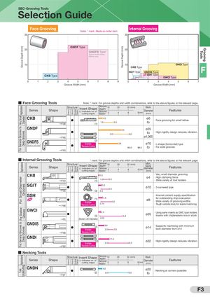
SEC-Grooving Tools Selection Guide Face Grooving Note: * mark: Made-to-order item. Internal Grooving 30 30 GNDF Type Groove Depth (mm) Groove Depth (mm) Grooving 20 20 GNDFS Type* Tools Groove width lineup 6/8mm only 10 10 GNDI Type F CKB Type SGIT Type GNDIS Type CKB Type SSH Type GWCI Type 0 1 2 3 4 5 6 7 8 9 0 1 2 3 4 5 6 7 Groove Width (mm) Groove Width (mm) ■ Face Grooving Tools Note: * mark: For groove depths and width combinations, refer to the above figures or the relevant page. Structure Insert Shape Groove Work For General Grooves to Very Small Applications 10 20 30 (mm) Depth* Series Shape Diameter Features Double Clamp-on Screw-on ( ): indicates no. of Groove Clamp cutting edges 2 4 6 8 (mm) (mm) Width* CKB Diameter 4.0 ø6 · Face grooving for small lathes →F38 (1) 1.5 3.0 to GNDF 23 ø35 to · High-rigidity design reduces vibration. Deep Grooves 3.0 6.0 →F40 ø1,000 (2) GNDFS Enables 20 ø70 · L-shape (horizontal) type Made-to-order item Traverse Cutting 6.0 8.0 to · For wide grooves →F43 ■ Internal Grooving Tools * mark: For groove depths and width combinations, refer to the above figures or the relevant page. Structure Insert Shape Groove Min. Applications 10 20 30 (mm) Depth* bore Series Shape Features Double Clamp-on 8 (mm) diameter Screw-on ( ): indicates no. of Groove 2 Clamp 4 6 cutting edges Width* (mm) CKB 1.0 ø4 · Very small diameter grooving · High clamping force For Small Diameter 1.0 2.0 →F44 (1) · Wide variety of tool holders SGIT Grooves 3.2 2.0 ø10 · 3-cornered type →F45 (3) 0.5 SSH 4.0 · Internal coolant supply specification for outstanding chip evacuation (1) ø8 3.0 · Wide variety of grooving widths Enables 0.74 Traverse Cutting · Tough carbide body for stable machining → F46 GWCI For General Grooves to For Shallow Grooves 2.5 · Using same inserts as GWC type holders (3) 4.8 ø35 · Inserts with chipbreakers now in stock →F5 (Standard, with Chipbreaker) 0.33 GNDIS 6.6 · Supports machining with minimum (2) ø14 Deep Grooves Enables 2.0 3.0 bore diameter from ø14 →F48 Traverse Cutting GNDI 11.0 (2) 2.0 6.0 ø32 · High-rigidity design reduces vibration. Enables →F50 Traverse Cutting ■ Necking Tools Structure Insert Shape Groove Undercutting Applications Depth* 10 20 30 (mm) Work Series Shape ( ): indicates no. of Diameter Features Double Clamp-on Screw-on Clamp Groove 2 4 6 8 (mm) cutting edges (mm) Width* GNDN 4.0 ø20 Face · Necking at corners possible (2) 2.0 6.0 to →F37 F3