| | Damage l | | Remedies |
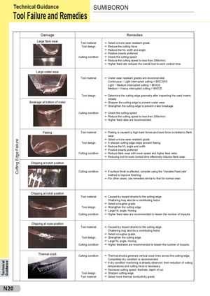
| | Large flank wear | Tool material Tool design Cutting condition | F F F F F F F Select a more wear resistant grade. Reduce the cutting force. Reduce the NL width and angle. Positive inserts preferred Check the cutting speed. Reduce the cutting speed to less than 200m/min. Higher feed rate reduces the overall tool-to-work contact time. |
| | Large crater wear | Tool material Tool design | F F Crater wear resistant grades are recommended. Continuous ~ Light interrupted cutting = BNC2010 Light ~ Medium interrupted cutting = BNX20 Medium ~ Heavy interrupted cutting = BNX25 Determine the cutting edge geometry after inspecting the used inserts |
| | Breakage at bottom of crater | Cutting condition | F F F F F closely. Sharpen the cutting edge to prevent crater wear. Strengthen the cutting edge to prevent crater breakage. Check the cutting speed. Reduce the cutting speed to less than 200m/min. Higher feed rates are recommended. |
| Edge Failure | Flaking | Tool material Tool design Cutting condition | F F F F F F F Flaking is caused by high back forces and back force is related to flank wear. Select a more wear resistant grade. A sharper cutting edge helps prevent flaking. Reduce the NL angle and width Positive inserts preferred Reduce flank wear with lower speed and higher feed rates. Reducing tool-to-work contact time effectively reduces flank wear. |
| Cutting | Chipping at notch position | Cutting condition | F F If surface finish is affected, consider using the “Variable Feed rate” method to improve finishing. For other cases, use remedies similar to that for normal wear. |
| | Chipping at notch position | Tool material Tool design Cutting condition | F F F F F Caused by impact shocks to the cutting edge. Chattering may also be a contributing factor. Select a tougher grade. Strengthen the cutting edge. Large NL angle, Honing. Higher feed rates are recommended to lessen the number of impacts. |
| | Chipping at nose position | Tool material Tool design Cutting condition | F F F F F Caused by impact shocks to the cutting edge. Chattering may also be a contributing factor. Select a tougher grade. Strengthen the cutting edge. Large NL angle, Honing. Higher feedrates are recommended to lessen the number of impacts. |
| Technical Guidance | | Thermal crack | Cutting condition Tool design Tool material | F F F F F Thermal shocks generate vertical crack lines across the cutting edge. Completely dry condition is recommended. If dry condition machining is already observed, then reduction of cutting temperatures and cutting force is necessary. Decrease cutting speed, feedrate, depth of cut. Sharpen cutting edge. Select more thermal conductivity grade. |
 Общий каталог Sumitomo 2012
 Каталог Sumitomo резьбонарезной инструмент
 Каталог Sumitomo пластины с режущей кромкой-моноалмаз Sumicristal
 Каталог Sumitomo инструмент для обработки канавок
 Общий каталог Sumitomo 2019 - 2020
 Каталог Sumitomo запасные части