Общий каталог Sumitomo 2018 - 2019 - страница 572
Навигация
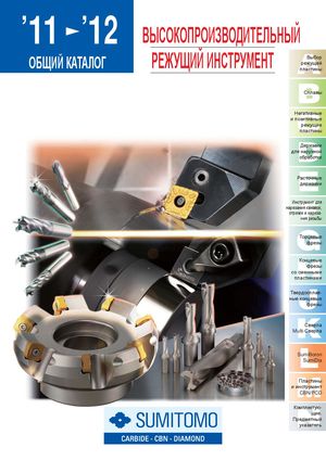 Общий каталог Sumitomo 2012
 Каталог Sumitomo резьбонарезной инструмент
 Каталог Sumitomo пластины с режущей кромкой-моноалмаз Sumicristal
 Каталог Sumitomo инструмент для обработки канавок
 Общий каталог Sumitomo 2019 - 2020
 Каталог Sumitomo запасные части
- Pages 3-6_CS6_EN_web
- A 1-20 insert selection EN_web
- B 1-14 grades_EN_web
- C01-17 inserts intro pages_EN_web
- C18-56 negative inserts_EN_web
- C57-86 positive inserts_EN_web
- D 1-46 tool holders_EN_web
- E 1-24 boring bars_EN_web
- F 1-48 grooving_thread tools_EN_web
- G 1-54 milling cutters_EN_web
- H 1-48 insert type endmills_EN_web
- J 1-24 new endmills_EN_web
- J 25-50 endmills_EN_web
- K 1-46 Multi-Drills_EN_web
- K 47-76 Multi-Drills_EN_web
- L 1-28 cbn_pcd grades_EN_web
- M 1-34 cbn_pcd inserts_EN_web
- M 35-56 SHM tools_EN_web
- N1-24 technical guidance_EN_web
- P 1-8 spare parts_neu_EN_web
- P 9-22 index_notes_EN_web
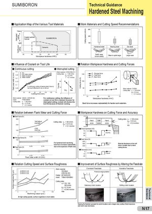
SUMIBORON Technical Guidance
Hardened Steel Machining
Application Map of the Various Tool Materials Work Materials and Cutting Speed Recommendations
Heavy Coated carbide SUMIBORON Cermet Light
Ceramic Hardened steel Bearing steel Die steel
| 40 | 55 50 45 60 | 65 | Notch wear | Large wear Wear is quite large. | |||
| Workpiece hardness (HRC) | occurs easily | ||||||
| Influence of Coolant on Tool Life | Relation Workpiece Hardness and Cutting Forces | ||||||
| Continuous cutting | Interrupted cutting | ||||||
| 0,3 | Work material: X155CrVMo12-1 | ||||||
| Dry | F | Principal force | |||||
| Non water soluble | Cutting data: vc = 100 m/min | 150 | 1 | F | |||
| 0,25 | F | Feed force | 2 | ||||
| Water emulsion | doc = 0,2 mm | 2 | |||||
| Water soluble | f = 0,1 mm/rev | F3 Back force |
0,2 F 3 0,15 100 F 1
0,1 In continuous cutting of bearing steel, there is
0,05 not much difference in dry or wet cut. 50 Work material: C105W1
| Dry | Wet | Cutting data: v | = 120 m/min | |
| 0 | c |
| 20 | 40 | 60 | 80 | 100 | 120 | 140 | doc = 0,2 mm | |||
| Cutting time (min) | f = 0,1 mm/rev | |||||||||
| 0 |
10 30 50 70
| Work material: 100Cr6 (HRC58~62) | For continuous cutting, the influence of | Workpiece hardness (HRC) |
| Insert: TPGN160304 | coolant on tool life is minimal. However for | |
| Cutting data: vc = 100 m/min | interrupted cutting, coolant will shorten the |
| d = 0,15 mm | tool life because of thermal cracking. | Back force increases substantially for harder work materials. | |
| oc | |||
| f = 0,1 mm/rev | |||
| Relation between Flank Wear and Cutting Force | Workpiece Hardness on Cutting Force and Accuracy | ||
| Back force (N) |
300 Cutting data: v = 120 m/min
Hard Soft Hard c
| 34CrMo4 | Cutting data: v | = 80 m/min | d | = 0,5 mm |
| oc |
| HRC65 | c | zone | zone | zone | f = 0,3 mm/rev | |
| d | = 0,15 mm |
200 oc dry
f = 0,1 mm/rev C55 Shore hardness (HS) 100 HRC24 70
50 45(HS) 0 30
Principal force (N) 0,05 0,10
Back force (N) 100 400 For hardened steel machining, External dimension at the soft
back force increases substantially 300 106N zone is smaller due to lower
0 due to the expansion of flank wear. 200
| Feed force (N) | 0,05 | 0,10 | cutting forces. | |
| 100 | Dimension (mm) | |||
| 0 | ||||
| -10 | ||||
| 0 | ||||
| 0,05 | 0,10 | -20 | ||
| Flank wear width VB (mm) | ||||
| Relation Cutting Speed and Surface Roughness | Improvement of Surface Roughness by Altering the Feedrate |
Work material: Constant Feedrate Variable Feedrate
BN250 Vc=120 25CrMo4 Previous edge position
BN250 Vc=150 (HRC58~62) ff
0,3 BN250 Vc=180 Holder: MTXNR2525 Insert: TNMA160408NU 0,2
Cutting data: v c= 120, 150,
| 0,1 | 180 m/min | Stationary notch location | Shifting notch location | |
| doc = 0,15 mm | ||||
| f = 0,045 mm/rev | ||||
| 0 | Wet |
0 40 80 120 160
Machining output (pcs.) At high cutting speeds, surface roughness is more stable.
Varying the feedrate spreads the notch location over a larger area, surface finish improves and notch wear decreases. N17