Общий каталог Sumitomo 2018 - 2019 - страница 569
Навигация
 Общий каталог Sumitomo 2012
 Каталог Sumitomo резьбонарезной инструмент
 Каталог Sumitomo пластины с режущей кромкой-моноалмаз Sumicristal
 Каталог Sumitomo инструмент для обработки канавок
 Общий каталог Sumitomo 2019 - 2020
 Каталог Sumitomo запасные части
- Pages 3-6_CS6_EN_web
- A 1-20 insert selection EN_web
- B 1-14 grades_EN_web
- C01-17 inserts intro pages_EN_web
- C18-56 negative inserts_EN_web
- C57-86 positive inserts_EN_web
- D 1-46 tool holders_EN_web
- E 1-24 boring bars_EN_web
- F 1-48 grooving_thread tools_EN_web
- G 1-54 milling cutters_EN_web
- H 1-48 insert type endmills_EN_web
- J 1-24 new endmills_EN_web
- J 25-50 endmills_EN_web
- K 1-46 Multi-Drills_EN_web
- K 47-76 Multi-Drills_EN_web
- L 1-28 cbn_pcd grades_EN_web
- M 1-34 cbn_pcd inserts_EN_web
- M 35-56 SHM tools_EN_web
- N1-24 technical guidance_EN_web
- P 1-8 spare parts_neu_EN_web
- P 9-22 index_notes_EN_web
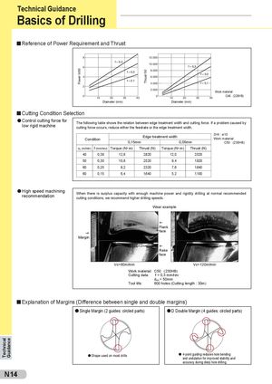
Reference of Power Requirement and Thrust
8 12.000 f = 0,3 10.000 6 f = 0,3 8.000
(kW f = 0,2 (N
f = 0,2 4 6.000 f = 0 1 4.000 f = 0,1
2 2.000 Work material:
0 0 C48 (220HB)
10 20 30 40 10 20 30 40
Diameter (mm) Diameter (mm) Cutting Condition Selection Control cutting force for low rigid machine The following table shows the relation between edge treatment width and cutting force. If a problem caused by
cutting force occurs, reduce either the feedrate or the edge treatment width.
| Con | dition | 0,15 | mm Edge trea | 0,05 tment width | mm | Drill : ø10 Work material: C50 (230HB) |
| vc (m/min) | f(mm/rev) | Torque (N• m) | Thrust (N) | Torque (N• m) | Thrust (N) | |
| 40 | 0,38 | 12,8 | 2.820 | 12,0 | 2.520 | |
| 50 | 0,30 | 10,8 | 2.520 | 9,4 | 1.920 | |
| 60 | 0,25 | 9,2 | 2.320 | 7,6 | 1.640 | |
| 60 | 0,15 | 6,4 | 1.640 | 5,2 | 1.100 |
High speed machining
recommendation When there is surplus capacity with enough machine power and rigidity drilling at normal recommended cutting conditions, we recommend higher drilling speeds. Wear example
f Flank face g Margin f Rake face Vc=60m/min Vc=120m/min Work material: C50 (230HB) Cutting data: f = 0,3 mm/rev d = 50mm oc Tool life: 600 holes (Cutting length : 30m)
Explanation of Margins (Difference between single and double margins)
Single Margin (2 guides: circled parts) D Double Margin (4 guides: circled parts)
Technical Guidance Shape used on most drills 4-point guiding reduces hole bending
and undulation for improved stability and accuracy during deep hole drilling.