Общий каталог Sumitomo 2018 - 2019 - страница 558
Навигация
 Общий каталог Sumitomo 2012
 Каталог Sumitomo резьбонарезной инструмент
 Каталог Sumitomo пластины с режущей кромкой-моноалмаз Sumicristal
 Каталог Sumitomo инструмент для обработки канавок
 Общий каталог Sumitomo 2019 - 2020
 Каталог Sumitomo запасные части
- Pages 3-6_CS6_EN_web
- A 1-20 insert selection EN_web
- B 1-14 grades_EN_web
- C01-17 inserts intro pages_EN_web
- C18-56 negative inserts_EN_web
- C57-86 positive inserts_EN_web
- D 1-46 tool holders_EN_web
- E 1-24 boring bars_EN_web
- F 1-48 grooving_thread tools_EN_web
- G 1-54 milling cutters_EN_web
- H 1-48 insert type endmills_EN_web
- J 1-24 new endmills_EN_web
- J 25-50 endmills_EN_web
- K 1-46 Multi-Drills_EN_web
- K 47-76 Multi-Drills_EN_web
- L 1-28 cbn_pcd grades_EN_web
- M 1-34 cbn_pcd inserts_EN_web
- M 35-56 SHM tools_EN_web
- N1-24 technical guidance_EN_web
- P 1-8 spare parts_neu_EN_web
- P 9-22 index_notes_EN_web
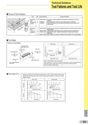
Tool Failures and Tool Life
Forms of Tool Failures
| Cat. | No. | Name of Failure | Cause of Failure |
| Resulting from Mechanical causes | 1~5 6 7 | Flank Wear Chipping Fracture | Due to the scratching effect of hard grains contained in the work material. Fine breakages caused by high cutting loads or chattering. Due to the impact of an excessive mechanical force acting on the cutting edge. |
| Resulting from Chemical reactions | 8 9 10 11 | Crater Wear Plastic Deformation Thermal Crack Built-up Edge | Swaft chips removing tool material as it flow over the top face at high temperatures. Cutting edge is depressed due to softening at high temperatures. Fatigue from rapid, repeated heating and cooling cycles during machining. Work material is pressure welded on the top face of the cutting edge. |
Tool Wear
Forms of Tool Wear
Flank wear Crater wear Bad chip control Cutting edge fracture Burrs occur Creater wear KT Initial wear
Poor surface finish Side flank wear Sudden
VN increase 1 in wear Face flank wear Steady wear VN
2 Flank wear VB Cutting Time T (min) Cutting Time T (min) Edge wear VC Higher cutting force Wear is rapid initially, then it proceeds Poor machining accuracy more gradually in proportion with Crater wear is more progressive with
Burrs occur cutting time until a certain limit, beyond no sudden breakdown pattern.
which it increases rapidly again.
Tool Life (V-T)
Measure the relative tool lives of the specified wear, over a range of cutting speeds, then plot the tool life along the X-axis and the cutting speed along the Y-axis on a double logarithm graph. Flank wear Crater wear
| V1 V2 | V3 | V | V | V | V | ||
| 1 | 2 | 3 | 4 | ||||
| V4 | |||||||
| VB | KT | ||||||
| T 1 T2 | T 3 | T 4 | T’ 1 T’2 | T’3 | T’ 4 | ||
| Cutting Time T (min) | Cutting Time T (min) | ||||||
| V | V1 | ||||||
| 1 | |||||||
| V | V2 | ||||||
| 2 | |||||||
| V | V3 | ||||||
| 3 | |||||||
| V | V4 | ||||||
| 4 | |||||||
| T 1 T 2 | T 3 | T 4 | T’1 | T’2 | T’ 3 | T’4 |
Tool life (min) Tool life (min)