Общий каталог Sumitomo 2018 - 2019 - страница 332
Навигация
 Общий каталог Sumitomo 2012
 Каталог Sumitomo резьбонарезной инструмент
 Каталог Sumitomo пластины с режущей кромкой-моноалмаз Sumicristal
 Каталог Sumitomo инструмент для обработки канавок
 Общий каталог Sumitomo 2019 - 2020
 Каталог Sumitomo запасные части
- Pages 3-6_CS6_EN_web
- A 1-20 insert selection EN_web
- B 1-14 grades_EN_web
- C01-17 inserts intro pages_EN_web
- C18-56 negative inserts_EN_web
- C57-86 positive inserts_EN_web
- D 1-46 tool holders_EN_web
- E 1-24 boring bars_EN_web
- F 1-48 grooving_thread tools_EN_web
- G 1-54 milling cutters_EN_web
- H 1-48 insert type endmills_EN_web
- J 1-24 new endmills_EN_web
- J 25-50 endmills_EN_web
- K 1-46 Multi-Drills_EN_web
- K 47-76 Multi-Drills_EN_web
- L 1-28 cbn_pcd grades_EN_web
- M 1-34 cbn_pcd inserts_EN_web
- M 35-56 SHM tools_EN_web
- N1-24 technical guidance_EN_web
- P 1-8 spare parts_neu_EN_web
- P 9-22 index_notes_EN_web
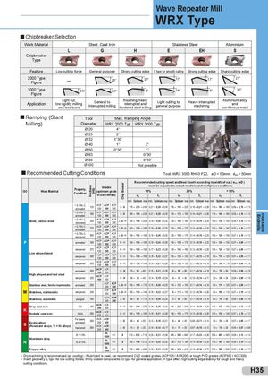
WRX Type
Chipbreaker Selection
Work Material Steel, Cast Iron Stainless Steel Aluminium
| L | G | H | E | EH | S | ||
| Chipbreaker | |||||||
| Type |
Feature Low cutting force General purpose Strong cutting edge E type for smooth cutting Strong cutting edge Sharp cutting edge
| 2000 Type | — | 20° | 17° | 17° | 27° | ||
| Figure | 28° | ||||||
| 3000 Type | 25° | 20° | 5° | 14° | 8° | 30° | |
| Figure |
Light cut, General to Roughing, heavy Light cutting to Heavy interrupted Aluminium alloy
Application low rigidity milling interrupted and and
and less burrs Interrupted milling hardened steel milling general purpose machining non-ferrous metal
| Tool | Max. Ram | pingAngle |
| Diameter | WRX 2000 Typ | WRX 3000 Typ |
| Ø 20 | 4° | |
| Ø 25 | 2° | |
| Ø 32 | 1°30’ | |
| Ø 40 | 1° | 2° |
| Ø 50 | 0°30’ | 1° |
| Ø 63 | 0°30’ | |
| Ø 80 | 0°30’ | |
| Ø100 | Notpossible |
Recommended Cutting Conditions
Tool: WRX 3050 RH53 F22, øD = 50mm, d = 50mm
oc
| Proert | ess ) | G | rade | s | eaker | Recomme - | nded cutting sp must be adjust | eed and feed / ed to actual m | tooth according achine and work | to width of cu piece conditio | t ( woc /øD ) ns. | |
| ISO Work Material | py, Condition | ardn (HB | (optim | um g | rade | p Br | 1 | 0% | 2 | 5% | > | 50% |
| H | in bo | ld let | ers) | hi | vc | f t | vc | f t | vc | f t | ||
| C | min. Optimum max | .min. Optimum max. | min. Optimum max | .min. Optimum max. | min. Optimum max | .min. Optimum max. | ||||||
| < 0,15% C, annealed | 125 | ACP 100 | ACP 200 | ACP 300 | L -G | 170– 215 –240 | 0,21– 0,28 –0,35 | 160– 195 –220 | 0,16– 0,21 –0,26 | 130– 160 –180 | 0,08– 0,10 –0,13 | |
| < 0,45% C, annealed | 190 | ACP 100 | ACP 200 | ACP 300 | L -G | 160– 195 –220 | 0,21– 0,28 –0,35 | 140– 175 –190 | 0,16– 0,21 –0,26 | 110– 140 –160 | 0,08– 0,10 –0,13 | |
| Steel, carbon steel | < 0,45% C, tempered | 250 | ACP 100 | ACP 200 | ACP 300 | L -G- H | 140– 180 –200 | 0,19– 0,26 –0,32 | 130– 165 –180 | 0,14– 0,19 –0,24 | 100– 130 –140 | 0,08– 0,10 –0,13 |
| < 0,75% C, annealed | 270 | ACP 100 | ACP 200 | ACP 300 | L -G- H | 140– 170 –190 | 0,19– 0,26 –0,32 | 120– 155 –170 | 0,14– 0,19 –0,24 | 100– 130 –140 | 0,07– 0,10 –0,12 | |
| < 0,75% C, tempered | 300 | ACP 100 | ACP 200 | ACP 300 | L -G- H | 130– 165 –180 | 0,19– 0,26 –0,32 | 120– 150 –170 | 0,14– 0,19 –0,24 | 100– 120 –130 | 0,07– 0,10 –0,12 | |
| P | annealed | 180 | ACP 100 | ACP 200 | ACP 300 | G- H | 130– 165 –180 | 0,18– 0,24 –0,30 | 120– 150 –170 | 0,13– 0,18 –0,22 | 100– 120 –130 | 0,07– 0,09 –0,11 |
| L lld tl | tempered | 275 | ACP 100 | ACP 200 | ACP 300 | G- H | 130– 160 –180 | 0,17– 0,23 –0,28 | 120– 145 –160 | 0,12– 0,16 –0,20 | 100– 120 –130 | 0,07– 0,09 –0,11 |
| ow aoye see | tempered | 300 | ACP 100 | ACP 200 | ACP 300 | G- H | 110– 140 –160 | 0,16– 0,22 –0,27 | 100– 130 –140 | 0,11– 0,15 –0,19 | 90– 110 –120 | 0,07– 0,09 –0,11 |
| tempered | 350 | ACP 100 | ACP 200 | ACP 300 | G- H | 100– 130 –140 | 0,16– 0,21 –0,26 | 100– 120 –130 | 0,11– 0,15 –0,19 | 80– 100 –110 | 0,06– 0,08 –0,10 | |
| Hihllddll | annealed | 200 | ACP 100 | ACP 200 | G -H | 70– 85 –90 | 0,15– 0,21 –0,26 | 60– 80 –90 | 0,11– 0,14 –0,18 | 60– 70 –80 | 0,06– 0,08 –0,10 | |
| g aoye an too stee | tempered | 325 | ACP 100 | ACP 200 | G -H | 30– 35 –40 | 0,14– 0,19 –0,24 | 30– 35 –40 | 0,10– 0,14 –0,17 | 20– 30 –30 | 0,06– 0,08 –0,10 | |
| Stainless steel, ferritic/martensitic | annealed | 200 | ACP 200 | ACP 300 | L -G- H | 120– 150 –170 | 0,15– 0,20 –0,25 | 110– 135 –150 | 0,11– 0,14 –0,18 | 90– 110 –120 | 0,07– 0,09 –0,11 | |
| M Stainless, martensitic | tempered | 240 | ACP 200 | ACP 300 | L -G- H | 100– 125 –140 | 0,16– 0,22 –0,27 | 90– 115 –130 | 0,12– 0,16 –0,20 | 80– 100 –110 | 0,07– 0,10 –0,12 | |
| Stainless, austenitic | plunged | 180 | ACM 200 | ACM 300 | L -G | 80– 95 –110 | 0,15– 0,20 –0,25 | 70– 85 –90 | 0,11– 0,14 –0,18 | 60– 70 –80 | 0,06– 0,08 –0,10 | |
| K Gray cast iron | GG | 180 | ACK 200 | ACK 300 | G- H | 190– 240 –270 | 0,19– 0,26 –0,32 | 180– 220 –240 | 0,14– 0,19 –0,24 | 140– 170 –190 | 0,09– 0,12 –0,15 | |
| Nodular cast iron | GGG | 250 | ACK 200 | ACK 300 | G- H | 140– 170 –190 | 0,16– 0,21 –0,26 | 120– 155 –170 | 0,12– 0,16 –0,20 | 100– 130 –140 | 0,07– 0,10 –0,12 | |
| Exotic alloys | Fe based, annelaed | 200 | ACK 200 | ACK 300 | L -G | 40– 45 –50 | 0,12– 0,16 –0,21 | 30– 40 –45 | 0,08– 0,11 –0,14 | 30– 35 –40 | 0,07– 0,09 –0,11 | |
| S (Resistant alloys, Ti + Ni alloys) | hardened | 280 | ACK 200 | ACK 300 | L -G | 15– 20 –25 | 0,10– 0,14 –0,17 | 10– 15 –20 | 0,07– 0,10 –0,12 | 10– 15 –20 | 0,05– 0,07 –0,09 | |
| Si < 13% | DL 1000 | H1 | S | 510– 635 –710 | 0,23– 0,31 –0,38 | 460– 580 –640 | 0,17– 0,22 –0,28 | 390– 485 –540 | 0,08– 0,12 –0,14 | |||
| N Aluminum alloy | Si≥13% | DL 1000 | H1 | S | 150– 190 –210 | 0,19– 0,25 –0,32 | 140– 175 –190 | 0,14– 0,18 –0,23 | 130– 165 –180 | 0,08– 0,10 –0,13 | ||
| Copper alloy | DL 1000 | H1 | S | 320– 405 –450 | 0,15– 0,21 –0,26 | 300– 370 –410 | 0,13– 0,16 –0,22 | 240– 300 –330 | 0,07– 0,10 –0,12 |
- Dry machining is recommended (air cooling) - if lubricant is used, we recommend CVD coated grades (ACP100 / ACK200) or tough PVD grades (ACP300 / ACK300). - Insert geometry: L type for low cutting forces, thinly coated components. G type for general application, H type offers high cutting edge stability for rough and heavy cutting conditions.