Общий каталог Sumitomo 2018 - 2019 - страница 287
Навигация
 Общий каталог Sumitomo 2012
 Каталог Sumitomo резьбонарезной инструмент
 Каталог Sumitomo пластины с режущей кромкой-моноалмаз Sumicristal
 Каталог Sumitomo инструмент для обработки канавок
 Общий каталог Sumitomo 2019 - 2020
 Каталог Sumitomo запасные части
- Pages 3-6_CS6_EN_web
- A 1-20 insert selection EN_web
- B 1-14 grades_EN_web
- C01-17 inserts intro pages_EN_web
- C18-56 negative inserts_EN_web
- C57-86 positive inserts_EN_web
- D 1-46 tool holders_EN_web
- E 1-24 boring bars_EN_web
- F 1-48 grooving_thread tools_EN_web
- G 1-54 milling cutters_EN_web
- H 1-48 insert type endmills_EN_web
- J 1-24 new endmills_EN_web
- J 25-50 endmills_EN_web
- K 1-46 Multi-Drills_EN_web
- K 47-76 Multi-Drills_EN_web
- L 1-28 cbn_pcd grades_EN_web
- M 1-34 cbn_pcd inserts_EN_web
- M 35-56 SHM tools_EN_web
- N1-24 technical guidance_EN_web
- P 1-8 spare parts_neu_EN_web
- P 9-22 index_notes_EN_web
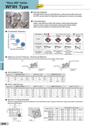
WFXH Type
General Features
WaveMill WFXH type is a high efficiency, multi-purpose cutter, that uses
the WFX series inserts for high-feed roughing and a variety of processes.
Characteristics
Stable, high-efficiency milling with superior cutting edge sharpness. Supports various types of processes (ramping and helical milling). Able to use the selection of inserts from the WFX series.
Chipbreaker Selection
| Work Material | P | M | K | Steel, Stainless Steel, Cast Iron | N | Aluminium Alloy | |||||||
| L | L Type | G Type | H Type | S Type | |||||||||
| Light Cutting | Breaker | ||||||||||||
| G | |||||||||||||
| General Purpose | H | Characteristic | Low Cutting Force | General Purpose | Strong Edge | Sharp Edge |
(Standard) Cutting Edge Heavy Cutting Figure Cutting Edge Strength High
Heavy Cut
Work Material Light Cutting Main Chipbreaker Heavy Interrupted
Low rigidity Milling General to Non-Ferrous Metal
| Application | Low-Burr Design | Interrupted Milling | Machining | ||
| Tempered Steel | |||||
| Notes on Corner Finishing - Remaining Material | |||||
| Actual machined corners will have uncut and overcut portions due to the shape of the inserts. |
Fig. 1 Fig. 2 Overcut Portion
Uncut Portion Uncut Portion Programmed Programmed Corner R Corner R
WFXH 08000 RS Type
Programmed SOMT 08 04- SOMT 08 08- SOMT 08 12-
| Corner R | Uncut Portion | Overcut Portion | Shape | Uncut Portion | Overcut Portion | Shape | Uncut Portion | Overcut Portion | Shape | |||||||
| 2,0 | 1,41 | 0 | Fig. 1 | 1,30 | 0 | Fig. 1 | 1,21 | 0 | Fig. 1 | |||||||
| 2,5 | 1,30 | 0,02 | Fig. 2 | 1,19 | 0,01 | Fig. 2 | 1,09 | 0 | Fig. 2 | |||||||
| 3,0 | - | - | - | - | - | - | 0,98 | 0,05 | Fig. 2 |
WFXH 12000 RS Type
| Programmed | SOM | T 12 04- | SOM | T 12 08- | SOM | T 12 12- | SOM | T 12 16 | - | |||
| Corner R | Uncut Portion | Overcut Portion | Shape | Uncut Portion | Overcut Portion | Shape | Uncut Portion | Overcut Portio | n Shape | Uncut Portion | Overcut Porti | on Shape |
| 2,0 | 2,58 | 0 | Fig. 1 | 2,48 | 0 | Fig. 1 | 2,37 | 0 | Fig. 1 | 2,25 | 0 | Fig. 1 |
| 2,5 | 2,47 | 0 | Fig. 1 | 2,37 | 0 | Fig. 1 | 2,25 | 0 | Fig. 1 | 2,14 | 0 | Fig. 1 |
| 3,0 | 2,36 | 0 | Fig. 1 | 2,26 | 0 | Fig. 1 | 2,14 | 0 | Fig. 1 | 2,11 | 0 | Fig. 1 |
| 3,5 | 2,24 | 0,01 | Fig. 2 | 2,14 | 0 | Fig. 1 | 2,03 | 0 | Fig. 1 | 1,91 | 0 | Fig. 1 |
| 4,0 | - | - | - | 2,03 | 0,04 | Fig. 2 | 1,91 | 0,03 | Fig. 2 | 1,8 | 0,01 | Fig. 2 |
Minimum Cutting Diameter
Minimum cutting diameter (DCN) will depend on the insert that is used. Using an insert with a large nose radius is recommended for the WFXH type. ØDb Ød
| BdCN | ØD | D | CN based | on insert no | se |
| oy at. o. | c | R0,4 | R0,8 | R1,2 | R1,6 |
| WFXH 08040 RS | 40 | 24,6 | 24,4 | 24,2 | - |
| 08050 RS | 50 | 34,6 | 34,4 | 34,2 | - |
| 08050 RSZ6 | 50 | 34,6 | 34,5 | 34,2 | - |
| 08063 RS | 63 | 47,6 | 47,5 | 47,2 | - |
| WFXH 12050 RS | 50 | 25,8 | 25,6 | 25,4 | 25,2 |
| 12063 RS | 63 | 38,6 | 38,4 | 38,2 | 38,0 |
ØDc