Каталог Stellram токарный инструмент - страница 203
Навигация
 Каталог Stellram материалы и сплавы
 Каталог Stellram твердосплавные цельные фрезы
 Каталог Stellram фрез со сменными пластинами
 Каталог Stellram высокопроизводительные фрезерные системы
 Каталог Stellram системы со сменными пластинами для фрезерования с высокими подачами
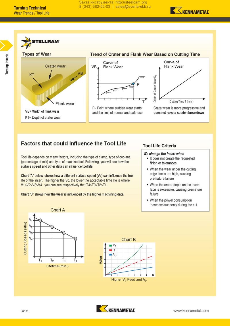
Заказ инструмента: http://steelcam.org Turning Technical 8 (343) 382-52-03 | sales@sverla-ekb.ru Wear Trends / Tool Life Inserts Types of Wear Trend of Crater and Flank Wear Based on Cutting Time Turning Crater wear CCuurrvveeooff CCuurvrveeoof f FClarnakteWr Weaerar VB FFlalannkkWWeeaarr DeptDhepotfhCrofateCrratWeerarWKTear KT KT VB P Flank wear T CCuutttitninggTiTmime Te (Tm(inm.)in.) VB= Width of flank wear P= Point where sudden wear starts Crater wear is more progressive and and the limit of normal and safe use does not have a sudden breakdown KT= Depth of crater wear Factors that could Influence the Tool Life Tool Life Criteria Tool life depends on many factors, including the type of clamp, type of coolant, We change the insert when (percentage of mix) and type of machine tool. Following, you will see how the • It does not create the requested surface speed and other data can influence tool life. finish or tolerances. • When the wear under the cutting Chart “A” below, shows how a different surface speed (Vc) can influence the tool edge line is too high, causing life of the insert. The higher the Vc, the lower the acceptable time life is where premature failure V1>V2>V3>V4 you can see respectively that T4>T3>T2>T1. • When the crater depth on the insert face is excessive, causing premature Chart “B” shows how the wear is influenced by the higher machining data. failure • When the power consumption increases suddenly during the cut CCharrtt AA CuCttuittnigngSpSepeedesd (ss(fsfm)m) V1 V2 V3 V4 CChart BB Vc f WWeeaarr Ap T1 T2 T3 T4 LLifiefetitmimee(m(minin.).) HHigighheerrVVccFFeeeeddaannddAApp C202 www.kennametal.com