Каталог Stellram фрез со сменными пластинами - страница 5
Навигация
 Каталог Stellram твердосплавные цельные фрезы
 Каталог Stellram токарный инструмент
 Каталог Stellram системы со сменными пластинами для фрезерования с высокими подачами
 Каталог Stellram высокопроизводительные фрезерные системы
 Каталог Stellram материалы и сплавы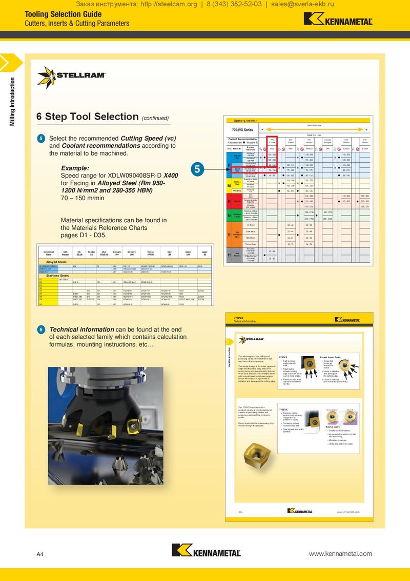
6 Step Tool Selection
(continued)
Select the recommended Cutting Speed (vc)
5
and Coolant recommendations according to
the material to be machined.
Example: 5
Speed range for XDLW090408SR-D X400
for Facing in Alloyed Steel (Rm 950-
1200 N/mm2 and 280-355 HBN)
70 – 150 m/min
Material specifications can be found in
the Materials Reference Charts
pages D1 - D35.
| UNS Commercial UK: | Sweden: | USA: | Germany: | Germany: | France: | Italy: | Spain: Japan: | ||
| Number Name BS,EN | SS | AISI/SAE | Wnr | DIN | AFNOR | UNI | UNF JIS | ||
| Alloyed Steels | |||||||||
| T4 / Z80WKCV18050401 | BT4 | T4 | 1.3255 | S18.1.2.5 | Z80WKCV18050401 | X78WCo1805KU | HS18.1.1.5 | SKH3 | |
| Z2NKDT18-10-5 | 1.2709 | X3NiCoMoTi18.9.5 | Z2NKDT18-10-5 | ||||||
| Z38CDV5-3 | 1.2367 | X40CrMoV53 | Z38CDV5-3 | Z155CVD12-1 | |||||
| Stainless Steels | |||||||||
| 50 | UNS S20910 | ||||||||
| 202 | 284S16 | 202 | 1.4371 | X3CrMnNiN18-8-7 | Z8CMN18.08.05 | ||||
| 215 | |||||||||
| 284 | |||||||||
| 301 | 2331 | 301 | 1.4310 | X12CrNi17-7 | Z12CN17.07 | X12CrNi17 07 | F.3517 | SUS301 | |
| 302 | 302S31 | 2330 | 302 | 1.4319 | X12CrNi18-9 | Z10CN18.09 | X10CrNi18 09 | F.314 | |
| 303 | 303S21, 58M | 2346 | 303 | 1.4305 | X8CrNiS18-9 | Z10CNF18.09 | X10CrNiS 18.09 | F.3508 | SUS303 |
| 304 | 304S31, 58E | 2332/2333 | 304 | 1.4350 | X5CrNi18-9 | Z6CN18.09 | X5CrNi18 10 | F.3551;F.3541;F.3504 | SUS304 |
| 305 | 305S19 | 305 | 1.4312 | X8CrNi18-12 | X8CrNi1910 | F.3503 | |||
| 311 | |||||||||
| 315 | |||||||||
| 316 | 316S33, 58J | 2343 | 316 | 1.4401 | X5CrNiMo17-13-3 | Z6CND19.12.03 | X5CrNiMo1713 | F.3543 | SUS316 |
| 317 | 317S16 | 317 | 1.4449 | X5CrNiMo17-13 | |||||
| 318 | 318 | 1.4583 | X10CrNiMoNb18-12 | Z6CNDNb17.13B | X6CrNiMoNb17 13 | ||||
| 320 | |||||||||
| 3216 | Technical information can be found at the end UNS S32100321S12, 58B23373211.4541X10CrNiTi18-9Z6CNT18.10X6CrNiTi18 11F.3553;F.3523 | SUS321 | |||||||
| 325 | |||||||||
| 326 | of each selected family which contains calculation | ||||||||
| 329 | 2324 | 329 | 1.4460 | X8CrNiMo27-5 | Z5CND27.05AZ | SUS329L | |||
| 331 | formulas, mounting instructions, etc… | ||||||||
| 332 | |||||||||
| 334 | 70334 | X8CrNiAlTi20-20 | |||||||
| 347 | UNS S34700 347S17, 58F | 2338 | 347 | 1.4550 | X10CrNiNb18-9 | Z6CNNb18.10 | X6CrNiNb18 11 | F.3552;F.3524 | SUS347 |
| 348 | UNS S34800 | 1.4546 | X5CrNiNb18-10 | Z10CrNiNb18 10 | |||||
| 394 | |||||||||
| 403 | 403S17 | 2301 | 403 | 1.4000 | X7Cr13 | Z6C13 | X6Cr13 | F.3110 | SUS403 |
| 409 | 409S19 | 409 | 1.4510 | X6CrTi12 | Z6CT12 | X6CrTi12 | |||
| 410 | 410S21, 56A | 2302 | 410 | 1.4006 | X10Cr13 | Z10C14 | X12Cr13 | F.3401 | SUS410 |
| 416 | 416S21 | 2380 | 41600 | 1.4005 | X12CrS13 | Z11CF13 | X12CrS13 | F.3411 | SUS416 |
| 420 | 420S37 | 2303 | 420 | 1.4021 | X20Cr13 | Z20C13 | X20Cr13 | F.5261 | |
| 425 | |||||||||
| 430 | 430S15, 60 | 2320 | 430 | 1.4016 | X8Cr17 | Z8C17 | X8Cr17 | F.3113 | SUS430 |
| 431 | 431S29, 57 | 2321 | 431 | 1.4057 | X22CrNi17 | Z15CNi16.02 | X16CrNi16 | F.3427 | SUS431 |
| 433 | |||||||||
| 434 | 434S17 | 2325 | 434 | 1.4113 | X6CrMo17 | Z8CD17.01 | X8CrMo17 | SUS434 | |
| 441 | |||||||||
| 444 | UNS S44400 | 2326 | 444 | 1.4521 | Z3CDT18 02 |
452 455 UNS S45500
Speed vc (m/min)
| -- | Wear Resistance | + | |
| 7792VX Series | |||
| Speed min. - max. | |||
| Coolant Recommendation |
| PVD | CVD | PVD | CVD Uncoated CVD | ||
| Recommended | Possible | X Grade | X Grade | Standard | Standard Micrograin Standard |
| Materials | Rm and | X400 | X500 | SP6519 | SC3025 GH2 SC6525 |
| ISO | Hardness | ||||
| <600 N/mm 2 | |||||
| Unalloyed | <180 HBN | 120 - 260 | 130 - 295 | 140 - 370 | |
| Steel | <950 N/mm 2 | | | | |
| <280 HBN | 105 - 230 | 115 - 260 | 120 - 325 | ||
| 700-950 N/mm2 | 95 - 200 | 100 - 210 | 100 - 230 | 105 - 290 | |
| P | 200-280 HBN | ||||
| Alloyed | 950-1200 N/mm2 | | | | |
| Steel | 280-355 HBN | 70 - 150 | 75 - 160 | 75 - 175 | 80 - 210 |
| 1200-1400 N/mm2 | 45 - 95 | 50 - 100 | 50 - 110 | 50 - 140 | |
| 355-415 HBN | | | | | |
| Austenitic + Ferritic | 115 - 250 | 115 - 270 | |||
| Stainless | 300 series | ||||
| Steel | Martensitic | | | ||
| M | 400 series | 100 - 220 | 105 - 235 | ||
| PH Stainless | Refractory | 50 - 110 | 50 - 120 | ||
| P.H. | |||||
| Grey | 140 - 295 | 150 - 395 145 - 390 | |||
| GG-Ft | |||||
| K Cast Iron | Spheroidal-Ductile | 110 - 240 | 120 - 335 115 - 305 | ||
| GGG-FGS | |||||
| Malleable | 100 - 220 | 105 - 275 | |||
| GTS - MN/MP | |||||
| Aluminium & Alloys | 305 - 2130 | 400 - 2745 | |||
| Aluminium | < 16% Si 116 HBN | ||||
| N & Alloys | | | |||
| Aluminium + Silicon | 245 - 1760 | 295 - 2135 | |||
| > 16% Si 92 HBN | |||||
| Iron Based | 23 - 48 | 23 - 55 | |||
| High | Cobalt Based | 21 - 44 | 22 - 48 | ||
| S Temperature | | | |||
| Alloys | Nickel Based | 24 - 51 | 25 - 55 | ||
| Titanium Based | 35 - 73 | 36 - 79 | |||
| Hard Steel | |||||
| >1400 N/mm2 | 45 - 95 | ||||
| Hard | >415 HBN | ||||
| H Materials | Chilled Cast Iron | |
>1400 N/mm2 35 - 80 > 400 HBN
7792VX
Technical Information
| The advantages of face milling and | 7792VX | Round Insert Tools |
| producing cavities with Stellram’s high | ||
| feed face mill are numerous. | • Cutting forces | • Tangential |
| predominantly | forces act | |
| The unique design of the insert, approach | axial | around the |
angle and the cutter body ensure the radius
- Relationship
| cutting forces are predominantly directed | between cutting | • Leads to vibration |
| in the axial direction. The example shown | edge and work piece | and damage of |
| with a round insert tool shows complex | is at its most stable. | the cutting edge |
| forces which result in high levels of | • Results in high feed | • Leads to reduced |
| vibration and damage to the cutting edge. | rates and consistent | feed and lower productivity |
tool life.
The 7792VX machines with a
| constant volume of chip throughout all | 7792VX | Side wall Centre clearance |
| aspects of producing cavities and | • Constant cutting | |
| produces a side wall that is close to | section (chip volume) | |
| profile. | irrespective of | |
| position in cavity. | ||
| Round insert tools have increasing chip | • Producing a close | |
| volume through the process. | to profile side wall. | Round insert |
- Near-square side walls
- Greater surface contact.
possible.
- Increased chip section for side
wall machining.
- Vibration in corners.
- Undulating side wall cusps.
A74 www.kennametal.com