Каталог Stellram фрез со сменными пластинами - страница 3
Навигация
 Каталог Stellram твердосплавные цельные фрезы
 Каталог Stellram токарный инструмент
 Каталог Stellram системы со сменными пластинами для фрезерования с высокими подачами
 Каталог Stellram высокопроизводительные фрезерные системы
 Каталог Stellram материалы и сплавы
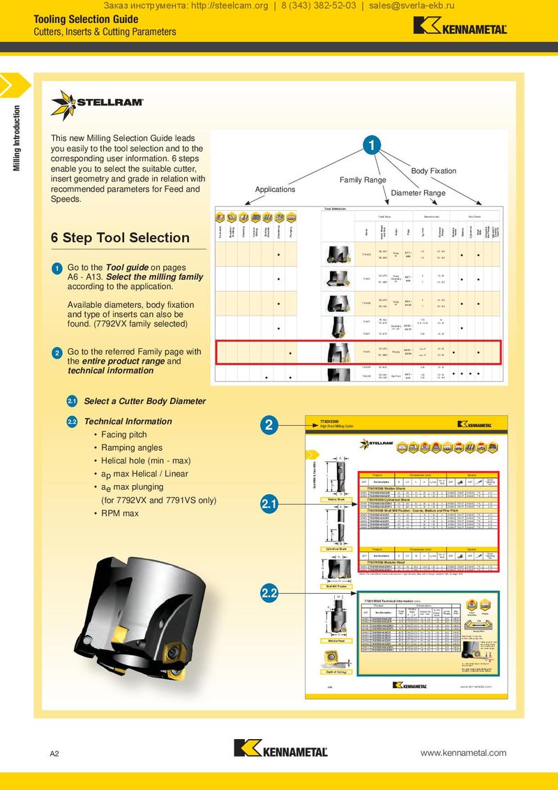
Заказ инструмента: http://steelcam.org | 8 (343) 382-52-03 | sales@sverla-ekb.ru Tooling Selection Guide Cutters, Inserts & Cutting Parameters Milling Introduction This new Milling Selection Guide leads 1 you easily to the tool selection and to the corresponding user information. 6 steps enable you to select the suitable cutter, Body Fixation insert geometry and grade in relation with Family Range recommended parameters for Feed and Applications Diameter Range Speeds. Application Tool Definition Family Range Dimensions (mm) Body Fixation 6 Step Tool SelectionFacingShoulder /Profiling /Slotting Ramping Pocketing HelicalInterpolation HelicalInterpolationwith Bore Hole Copy / 3D Spiral / Circular Trochoidal Shoulder / Profiling T-Slotting Contour Milling Slotting Shoulder Chamfering Plunging Series Insert Shape and Size Angle Page ap max DiameterRange ModularHeads Weldon Cylindrical ShellMills CaterpillarVee Flange DIN 69871 FixationTaper 50 • • • • • • • • • OD..0404 Facing A77 - 3,5 25 - 160 • • 7745VOD 42° A86 OD..0605 4,5 50 - 160 1 Go to the Tool guide on pages A6 - A13. Sele•ct the milling family • SC..09T3 Facing A87 - 5 16 - 25 • • 7745VS Chamfering A94 according to the application. SC..12M5 45° 7 40 - 125 Available diam•eters, •body fixation • • SD..09T3 Facing A95 - 5 16 - 125 • • 7745VSE 45° A105 SD..1204 7 50 - 125 and type of inserts can also be found. (7792VX family selected) 7745VT TP..1102 7,70 16 TC..16T3 6,10 - 11,30 20 - 30 • Chamfering A265 - • 45° / 60° A270 7760VT TC..16T3 9,50 16 - 25 Go to the referred Family page with • SC..09T3 A257 - ae = 8 25 - 50 • • 2 7791VS Plunging A264 SC..12M5 ae = 11 63 - 80 the entire product range and technical information 7792VXP XP..0603 0,90 16 - 32 • • • • • • • • • 7792VXD XD..0904 High Feed A63 - 1,50 25 - 50 • • • • XD..1205 A75 2,50 32 - 160 7792VXE XE..1605 3,50 63 - 160 2.1 Select a Cutter Body Diameter Tungsten • Cylindrical Shank - - A76 - 16 - 32 Extensions 2.2 Technical Information 2 7792VXD09 High Feed Milling Cutter • Facing pitch • Ramping angles • Helical hole (min - max) d1 • ap max Helical / Linear End Mills & Face Mills L Product Dimensions (mm) Spares No. of Screw EDP Item Description D L/H l1 d1 ap max Teeth EDP EDP Tightening • ae max plunging I1 Nm 7792VXD09 Weldon Shank D 029461 7792VXD09WA025Z2R 25 96 40 25 1,50 2 015269 F3508T 015240 T15 2,10 (for 7792VX and 7791VS only) 029462 7792VXD09WA032Z3R 32 100 40 32 1,50 3 015064 F3510T 015240 T15 2,10 2.1 Weldon Shank 7792VXD09 Cylindrical Shank 031191 7792VXD09CA025Z2R50 25 200 50 25 1,50 2 015064 F3510T 015240 T15 2,10 d1 031192 7792VXD09CA032Z3R70 32 250 70 32 1,50 3 015064 F3510T 015240 T15 2,10 • RPM max 7792VXD09 Shell Mill Fixation - Coarse, Medium and Fine Pitch 029463 7792VXD09-A040Z3R 40 32 - 16 1,50 3 015064 F3510T 015240 T15 2,10 029464 7792VXD09-A040Z4R 40 32 - 16 1,50 4 015064 F3510T 015240 T15 2,10 L 030434 7792VXD09-A040Z5R 40 32 - 16 1,50 5 015064 F3510T 015240 T15 2,10 030435 7792VXD09-A050Z5R 50 40 - 22 1,50 5 015064 F3510T 015240 T15 2,10 030436 7792VXD09-A050Z6R 50 40 - 22 1,50 6 015064 F3510T 015240 T15 2,10 I1 D Cylindrical Shank Product Dimensions (mm) Spares No. of Screw d1 EDP Item Description D L/H M d1 ap max Teeth EDP EDP Tightening Nm 7792VXD09 Modular Head H 030613 7792VXD09SA025Z2R35 25 35 M12 12,50 1,50 2 015269 F3508T 015240 T15 2,10 030614 7792VXD09SA032Z3R43 32 43 M16 17,00 1,50 3 015064 F3510T 015240 T15 2,10 Note: For cylindrical shank extensions in high density alloy with through coolant refer to page A76. D Shell Mill Fixation 2.2 M 7792VXD09 Technical Information (mm) d1 Product Dimensions Ramping ap max EDP Item Description Facing Angle Helical Hole Helical / ae max Max Helical Pitch A° B° min. - max. Linear Plunging RPM Interpolation Plunging 029461 7792VXD09WA025Z2R 11,75 2.80 6.30 34 48 1,00 6,00 48500 Flat L 029462 7792VXD09WA032Z3R 18,75 1.50 5.00 48 62 1,00 6,00 40500 031191 7792VXD09CA025Z2R50 11,75 2.80 6.30 34 48 1,00 6,00 48500 031192 7792VXD09CA032Z3R70 18,75 1.50 5.00 48 62 1,00 6,00 40500 029463 7792VXD09-A040Z3R 26,75 0.80 2.70 64 78 1,00 6,00 34500 Facing Pitch D 029464 7792VXD09-A040Z4R 26,75 0.80 2.70 64 78 1,00 6,00 34500 Ramp angle A uses one 030434 7792VXD09-A040Z5R 26,75 0.80 2.70 64 78 1,00 6,00 34500 outside cutting edge only. Modular Head 030435 7792VXD09-A050Z5R 36,75 0.71 2.31 84 98 1,00 6,00 30000 Ramp angle B uses 030436 7792VXD09-A050Z6R 36,75 0.71 2.31 84 98 1,00 6,00 29500 two cutting edges 030613 7792VXD09SA025Z2R35 11,75 2.80 6.30 34 48 1,00 6,00 48500 (one outside and one inside edge). 030614 7792VXD09SA032Z3R43 18,75 1.50 5.00 48 62 1,00 6,00 40500 A B ap A = max ramp angle utilising full face contact B = max ramp angle utilising full Depth of Cut (ap) contact + internal corner radius A66 www.kennametal.com A2 www.kennametal.com