Общий каталог PRECITOOL - страница 550
Навигация
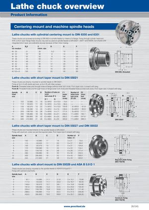
DLaiethGelicehduecrkunogvedrewsieKwataloges SPcrohdnuecllteInÜfboerrmsaicthiotnfür eine einfache Bestellung Centering mount and machine spindle heads Lathe chucks with cylindrial centering mount to DIN 6350 and 6351 These chucks are screwed according to DIN 800 to spindle heads by means of a flange. Fixing through cylinder head bolt. With a short taper flange these chucks may well be used on spindle heads to DIN 55021, 55011 and 55029, but chucks with integrated short taper are preferable anyway because of their minor nosing. A Bg5 C D E F tol.-medium minim. size M 20 21 30 6,3 10 20 M 24 25 36 8 12 24 M 33 34 50 9 14 30 M 39 40 56 10 16 35 M 45 46 67 11 18 40 M 52 55 80 12 20 45 M 60 62 90 14 22 50 M 76 × 6 78 112 16 30 63 M 105 × 6 106 150 20 40 80 DIN 800, threaded Lathe chucks with short taper mount to DIN 55021 These chucks are directly mounted to spindle heads to DIN 55021. Fixing at form A with studs and nuts. at form B with Allan screws. Form A: Threaded holes and through holes at flange (without inner bolt circle). From taper size 4 onward with tang. Form B: Threaded holes and through holes at flange (outer bolt circle) and threaded holes at inner bolt circle. From taper size 4 onward with tang. Spindle A B C D Number of holes on F1 Number of F2 head outer (outer holes inner (inner size bolt circle (F 1) bolt bolt circle bolt E1 G circle) (F1) E2 circle) 3 102 53.985 11 16 3 × M10 3 × 10.5 75.0 — — 4 112 63.525 11 20 3 × M10 3 × 10.5 85.0 — — 5 135 82.575 13 22 7 × M10 4 × 10.5 104.8 8 × M10 61.9 6 170 106.390 14 25 7 × M12 4 × 13 133.4 8 × M12 82.6 8 220 139.735 16 28 7 × M16 4 × 17 171.4 8 × M16 111.1 11 290 196.885 18 35 12 × M20 6 × 21 235.0 11 × M20 165.1 15 380 285.800 20 42 12 × M24 6 × 25 330.2 11 × M24 247.6 20 520 412.800 21 48 12 × M24 6 × 25 463.6 11 × M24 368.3 DIN 55021 Lathe chucks with short taper mount to DIN 55027 und DIN 55022 These chucks are mounted directly to the spindle heads to DIN 55027. Fixing with stud bolt. collar nut and the bayonet plate. From taper size 4 onward with tang. Spindle head A B C D Number of F size holes × E 3 102 53.985 11 16 3 × 21 75.0 4 112 63.525 11 20 3 × 21 85.0 5 135 82.575 13 22 4 × 21 104.8 6 170 106.390 14 25 4 × 23 133.4 8 220 139.735 16 28 4 × 29 171.4 11 290 196.885 18 35 6 × 36 235.0 15 400 285.800 19 42 6 × 43 330.2 20 540 412.800 21 48 6 × 43 463.6 Bayonet plate fixing (ISO 702/III) Lathe chucks with short mount to DIN 55029 und ASA B 5.9 D 1 These chucks are directly mounted to the spindle heads to ASA B 5.9 type D 1. Fixing with camlock stud bolts. Spindle head A B C D E F size 3 92.1 53.985 11.1 31.8 3 × 15.1 70.66 4 117.5 63.525 11.1 33.3 3 × 16.7 82.55 5 146.0 82.575 12.7 38.1 6 × 19.8 104.80 6 181.0 106.390 14.3 44.5 6 × 23.0 133.40 8 225.4 139.735 15.9 50.8 6 × 26.2 171.40 11 298.5 196.885 17.5 60.3 6 × 31.0 235.00 15 403.0 285.800 19.0 69.9 6 × 35.7 330.20 Camlock fixing (ISO 702/III) www.precitool.de 26/545