Общий каталог PRECITOOL - страница 316
Навигация
Polycrystalline diamond (PCD)
Properties PCD
Eigenschaften
| Diamond, known as the hardest | PCD diamond cutting plates are used in the processing of non-ferrous | ||
| material, is present here as a sin- | metals [aluminium alloys, copper alloys] and non-metals [fibre-reinforced | ||
| tered polycrystalline diamond layer. CBN | plastics (GRP, CRP), hard rubber, wood, multilayer laminates (fibre | ||
| By means of a high-temperature | boards, melamine resin composites), fibre particle reinforced metals | ||
| high-pressure process, a dense, | (MMC )]. | ||
| homogeneous layer of polycrys- | The use of PCD-equipped tools ensures the highest cutting speeds, | ||
| talline diamonds is applied to hard | service life, surface finishes and dimensional accuracies. | ||
| metal as carrier material. | |||
| Application | |||
| Diamant bekannt als das härteste Material, liegt hier als | PKD Diamantschneidplatten finden Anwendung in der | ||
| BDA 23 | PCD fine-grain, increased surface requirements fine-eroding toolsgesinterte polykristalline Diamantschicht vor. Mit Hilfe Bearbeitung von Nicht-Eisen-Metallen [Aluminium- | ||
| eines speziellen Hochdruck-Hochtemperatur-Verfahrens | legierungen, Kupferlegierungen] und Nicht-Metallen | ||
| BDA 18 | PKD medium grain, standard PCD quality, AlSi max. 12 %wird eine dichte Lage aus polykristallinen Diamanten auf [faserverstärkte Kunststoffe (GFK, CFK), Hartgummi, | ||
| Hartmetall als Trägermaterial aufgebracht. | Holz, Mehrlagen-Schichtverbunde (Faserplatten, |
BDA 16 PCD mixed grain, increased wear resistance, AlSi> 12 %, with a high proportion of abrasive fillersMelaminharz-Verbundstoffe), Faserpartikelverstärkte Metalle (MMC)]. Durch den Einsatz von PKD bestückten Werkzeugen werden höchste Schnittgeschwindigkei- ten, Standzeiten, Oberflächengüten und Maßgenau-
igkeiten erreicht.
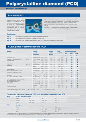
Cutting data recommendations PCD
| Material | Cutting | Cutting | Feed | Recom | mended t | ype | ||
| speed | depth | f mm/U | ||||||
| V (m/min.) | ap mm | BDA 23 | BDA 18 | BDA 16 | ||||
| Aluminium alloys: | Rough turning | 800 – 3.000 | 0.3 – 5.0 | 0.1 – 0.6 | ■ | |||
| Aluminium, cast aluminium and | Si | Finish turning | 800 – 3.000 | 0.05 – 1.0 | 0.03 – 0.2 | ■ | ■ | |
| moulded cast | Milling | 800 – 3.500 | 0.1 – 2.5 | 0.05 – 0.3 | ■ | |||
| Rough turning | 300 – 900 | 0.1 – 2.5 | 0.1 – 0.4 | ■ | ||||
| High-silicon aluminium | Si >12 % | Finish turning | 300 – 900 | 0.05 – 0.8 | 0.03 – 0.2 | ■ | ||
| Milling | 400 – 1.000 | 0.1 – 2.0 | 0.05 – 0.3 | ■ | ■ | |||
| Copper alloys: | Rough turning | 600 – 1,200 | 0.5 – 2.0 | 0.1 – 0.4 | ■ | |||
| Bronze, brass, tinplate, copper, | Finish turning | 700 – 1.500 | 0.05 – 0.5 | 0.05 – 0.4 | ■ | ■ | ||
| zinc alloys, magnesium alloys | Milling | 700 – 1.200 | 0.1 – 2.5 | 0.1 – 0.3 | ■ | |||
| Carbides | Rough turning | 20 – 25 | 0.1 – 0.5 | 0.1 – 0.3 | ■ | |||
| up to max. 15% cobalt content | Finish turning | 20 – 30 | 0.05 – 0.2 | 0.05 – 0.2 | ■ | |||
| Hard rubber, glass, ceramics, graph- | Rough turning | 80 – 1,000 | 1.0 – 5.0 | 0.1 – 0.4 | ■ | |||
| ite, All plastics, PVC, PA, PE, Fibre reinforced plastics | Finish turning | 80 – 1,500 | 0.1 – 2.0 | 0.05 – 0.3 | ■ | ■ | ||
| (GRP, CRP) | Finish turning | 200 – 1,000 | 0.1 – 5.0 | 0.1 – 0.3 | ■ | ■ | ||
| Wd it | Sawing | 2,000 – 5,000 | 0.05 – 1.0 | ■ | ■ | |||
| oo composes | Milling | 2,000 – 5.000 | 0.05 – 1.0 | ■ | ■ |
* Feed rates for milling = mm / tooth | ■ = particularly suitable | = conditionally suitable
Cutting data recommendation for PCD tools with chip breaker MED and ROF
| MED: | for fine - medium | i machining | ||
| Radius | R0.2 | R0.4 | R0.8 | |
| f mm/U | 0.04 - 0.1 | 0.08 - 0.2 | 0.1 - 0.3 | |
| ap mm | 0.05 - 0.6 | 0.1 - 2.0 | 0.3 - 2.5 | |
| ROF: | for roughing | |||
| Radius | R0.4 | R0.8 | ||
| f mm/U | 0.1 - 0.25 | 0.15 - 0.35 | ||
| ap mm | 0.4 - 2.0 | 0.6 - 3.0 |
The values given are only approximations. The processing should start with the average value of the recommended cutting data, then the cutting values can be changed (according to the chip shape and surface quality) in order to optimize the machining.