Общий каталог Osawa 2018 - страница 450
Навигация
 Общий каталог Osawa 2021
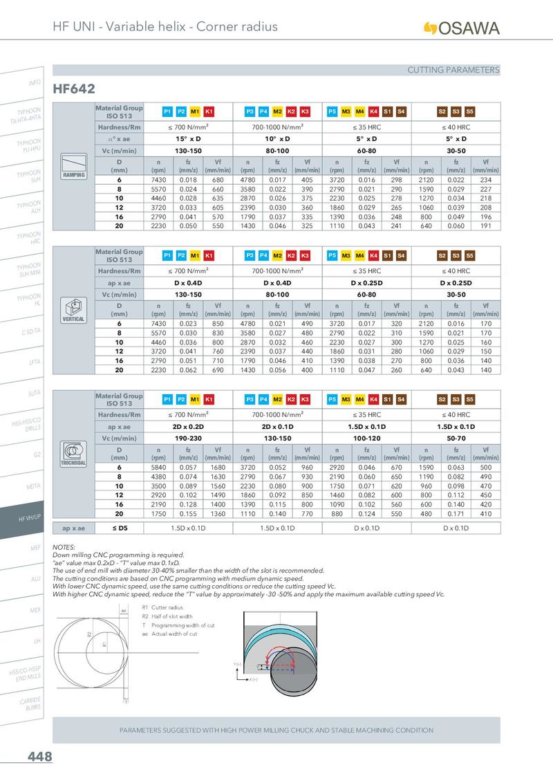
HF UNI - Variable helix - Corner radius CUTTING PARAMETERS INFO HF642 TA-THYTPAH-4OHOTNA Material Group P1 P2 M1 K1 P3 P4 M2 K2 K3 P5 M3 M4 K4 S1 S4 S2 S3 S5 ISO 513 Hardness/Rm ≤ 700 N/mm² 700-1000 N/mm² ≤ 35 HRC ≤ 40 HRC TYPPHUO-HOPNU _° x ae 15° x D 10° x D 5° x D 5° x D Vc (m/min) 130-150 80-100 60-80 30-50 D n fz Vf n fz Vf n fz Vf n fz Vf TYPHOSOUNH RAMPING (mm) (rpm) (mm/z) (mm/min) (rpm) (mm/z) (mm/min) (rpm) (mm/z) (mm/min) (rpm) (mm/z) (mm/min) 6 7430 0.018 680 4780 0.017 405 3720 0.016 298 2120 0.022 234 8 5570 0.024 660 3580 0.022 390 2790 0.021 290 1590 0.029 227 TYPHOAOLNH 10 4460 0.028 635 2870 0.026 375 2230 0.025 278 1270 0.034 218 12 3720 0.033 605 2390 0.030 360 1860 0.029 265 1060 0.039 208 16 2790 0.041 570 1790 0.037 335 1390 0.036 248 800 0.049 196 20 2230 0.050 550 1430 0.046 325 1110 0.043 241 640 0.060 191 TYPHOHORNC Material Group P1 P2 M1 K1 P3 P4 M2 K2 K3 P5 M3 M4 K4 S1 S4 S2 S3 S5 TSYUPHHOMOINNI ISO 513 Hardness/Rm ≤ 700 N/mm² 700-1000 N/mm² ≤ 35 HRC ≤ 40 HRC ap x ae D x 0.4D D x 0.4D D x 0.25D D x 0.25D TYPHOOHNL Vc (m/min) 130-150 80-100 60-80 30-50 D n fz Vf n fz Vf n fz Vf n fz Vf VERTICAL (mm) (rpm) (mm/z) (mm/min) (rpm) (mm/z) (mm/min) (rpm) (mm/z) (mm/min) (rpm) (mm/z) (mm/min) 6 7430 0.023 850 4780 0.021 490 3720 0.017 320 2120 0.016 170 C-SD-TA 8 5570 0.030 830 3580 0.027 480 2790 0.022 310 1590 0.021 170 10 4460 0.036 800 2870 0.032 460 2230 0.027 300 1270 0.025 160 12 3720 0.041 760 2390 0.037 440 1860 0.031 280 1060 0.029 150 LFTA 16 2790 0.051 710 1790 0.046 410 1390 0.038 270 800 0.036 140 20 2230 0.062 690 1430 0.056 400 1110 0.047 260 640 0.043 140 SUTA Material Group P1 P2 M1 K1 P3 P4 M2 K2 K3 P5 M3 M4 K4 S1 S4 S2 S3 S5 ISO 513 HSS-HDSSR/ILCLOS Hardness/Rm ≤ 700 N/mm² 700-1000 N/mm² ≤ 35 HRC ≤ 40 HRC ap x ae 2D x 0.2D 2D x 0.1D 1.5D x 0.1D 1.5D x 0.1D Vc (m/min) 190-230 130-150 100-120 50-70 G2 D n fz Vf n fz Vf n fz Vf n fz Vf TROCHOIDAL (mm) (rpm) (mm/z) (mm/min) (rpm) (mm/z) (mm/min) (rpm) (mm/z) (mm/min) (rpm) (mm/z) (mm/min) 6 5840 0.057 1680 3720 0.052 960 2920 0.046 670 1590 0.063 500 8 4380 0.074 1630 2790 0.067 930 2190 0.060 650 1190 0.082 490 MDTA 10 3500 0.089 1560 2230 0.080 900 1750 0.071 620 960 0.098 470 12 2920 0.102 1490 1860 0.092 850 1460 0.082 600 800 0.112 450 16 2190 0.128 1400 1390 0.115 800 1090 0.102 560 600 0.140 420 HF VH/UP 20 1750 0.155 1360 1110 0.140 770 880 0.124 550 480 0.171 410 ap x ae ≤ D5 1.5D x 0.1D 1.5D x 0.1D D x 0.1D D x 0.1D MEF NOTES: Down milling CNC programming is required. “ae” value max 0.2xD - “T” value max 0.1xD. The use of end mill with diameter 30-40% smaller than the width of the slot is recommended. ALU The cutting conditions are based on CNC programming with medium dynamic speed. With lower CNC dynamic speed, use the same cutting conditions or reduce the cutting speed Vc. With higher CNC dynamic speed, reduce the “T” value by approximately -30 -50% and apply the maximum available cutting speed Vc. MEX ae R1 Cutter radius R2 Half of slot width T Programming width of cut R2 ae Actual width of cut UH R1 HSSE/NCDO-MHISLSLPS Y (+) Y X (+) CARBIDE T BURRS PARAMETERS SUGGESTED WITH HIGH POWER MILLING CHUCK AND STABLE MACHINING CONDITION 448