Общий каталог Osawa 2018 - страница 410
Навигация
 Общий каталог Osawa 2021
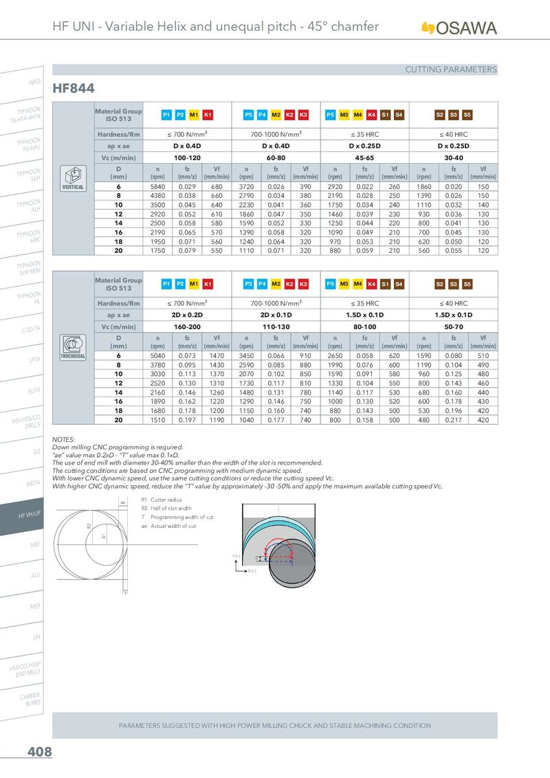
HF UNI - Variable Helix and unequal pitch - 45° chamfer CUTTING PARAMETERS INFO HF844 TA-THYTPAH-4OHOTNA Material Group P1 P2 M1 K1 P3 P4 M2 K2 K3 P5 M3 M4 K4 S1 S4 S2 S3 S5 ISO 513 Hardness/Rm ≤ 700 N/mm² 700-1000 N/mm² ≤ 35 HRC ≤ 40 HRC TYPPHUO-HOPNU ap x ae D x 0.4D D x 0.4D D x 0.25D D x 0.25D Vc (m/min) 100-120 60-80 45-65 30-40 TYPHOSOUNH D n fz Vf n fz Vf n fz Vf n fz Vf (mm) (rpm) (mm/z) (mm/min) (rpm) (mm/z) (mm/min) (rpm) (mm/z) (mm/min) (rpm) (mm/z) (mm/min) VERTICAL 6 5840 0.029 680 3720 0.026 390 2920 0.022 260 1860 0.020 150 8 4380 0.038 660 2790 0.034 380 2190 0.028 250 1390 0.026 150 TYPHOAOLNH 10 3500 0.045 640 2230 0.041 360 1750 0.034 240 1110 0.032 140 12 2920 0.052 610 1860 0.047 350 1460 0.039 230 930 0.036 130 14 2500 0.058 580 1590 0.052 330 1250 0.044 220 800 0.041 130 TYPHOHORNC 16 2190 0.065 570 1390 0.058 320 1090 0.049 210 700 0.045 130 18 1950 0.071 560 1240 0.064 320 970 0.053 210 620 0.050 120 20 1750 0.079 550 1110 0.071 320 880 0.059 210 560 0.055 120 TSYUPHHOMOINNI Material Group P1 P2 M1 K1 P3 P4 M2 K2 K3 P5 M3 M4 K4 S1 S4 S2 S3 S5 ISO 513 TYPHOOHNL Hardness/Rm ≤ 700 N/mm² 700-1000 N/mm² ≤ 35 HRC ≤ 40 HRC ap x ae 2D x 0.2D 2D x 0.1D 1.5D x 0.1D 1.5D x 0.1D C-SD-TA Vc (m/min) 160-200 110-130 80-100 50-70 D n fz Vf n fz Vf n fz Vf n fz Vf (mm) (rpm) (mm/z) (mm/min) (rpm) (mm/z) (mm/min) (rpm) (mm/z) (mm/min) (rpm) (mm/z) (mm/min) LFTA TROCHOIDAL 6 5040 0.073 1470 3450 0.066 910 2650 0.058 620 1590 0.080 510 8 3780 0.095 1430 2590 0.085 880 1990 0.076 600 1190 0.104 490 10 3030 0.113 1370 2070 0.102 850 1590 0.091 580 960 0.125 480 12 2520 0.130 1310 1730 0.117 810 1330 0.104 550 800 0.143 460 SUTA 14 2160 0.146 1260 1480 0.131 780 1140 0.117 530 680 0.160 440 16 1890 0.162 1220 1290 0.146 750 1000 0.130 520 600 0.178 430 18 1680 0.178 1200 1150 0.160 740 880 0.143 500 530 0.196 420 HSS-HDSSR/ILCLOS 20 1510 0.197 1190 1040 0.177 740 800 0.158 500 480 0.217 420 NOTES: G2 Down milling CNC programming is required. “ae” value max 0.2xD - “T” value max 0.1xD. The use of end mill with diameter 30-40% smaller than the width of the slot is recommended. The cutting conditions are based on CNC programming with medium dynamic speed. MDTA With lower CNC dynamic speed, use the same cutting conditions or reduce the cutting speed Vc. With higher CNC dynamic speed, reduce the “T” value by approximately -30 -50% and apply the maximum available cutting speed Vc. ae R1 Cutter radius HF VH/UP R2 Half of slot width T Programming width of cut R2 ae Actual width of cut R1 MEF Y (+) Y ALU X (+) T MEX UH HSSE/NCDO-MHISLSLPS CARBIDE BURRS PARAMETERS SUGGESTED WITH HIGH POWER MILLING CHUCK AND STABLE MACHINING CONDITION 408