Общий каталог Lamina Technologies 2019 - 2020 - страница 186
Навигация
 Общий каталог Lamina Technologies 2017 - 2018
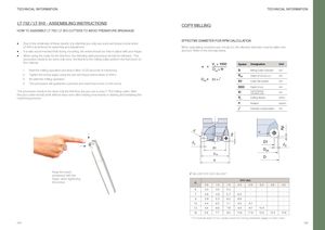
TECHNICAL INFORMATION TECHNICAL INFORMATION LT 752 / LT 910 - ASSEMBLING INSTRUCTIONS COPY MILLING HOW TO ASSEMBLY LT 752 / LT 910 CUTTERS TO AVOID PREMATURE BREAKAGE • Due to the small size of these inserts, it is vital that you only use a pre-set torque screw driver EFFECTIVE DIAMETER FOR RPM CALCULATION n = Vc x 1000Deff x π (0.4Nm) at all times for assembly and adjustment.•It is also recommended that during mounting, the insert should be held in place with your finger.When calculating account. Refer to revolution per minute the formula below. (n), the effective diDameff e=terDm1u+slt be taken into • When using the cutter for the first time, the following start procedure should be followed. This procedure needs to be done only once, the first time the milling cutter perform the first touch on the material.1.Start the milling operation and stop it after 10-20 seconds of machining n = Vc x 1000Deff x π Symbol Designation UnitDMilling Cutter Diametermm 2. Tighten the screw again using the pre-set torque screw driver (0.4Nm) Deff Depth of cut (d.o.c.) mm 3. Re-start the milling operation Deff = D1 + l D1 Cutter flat surface mm 4. This procedure will guarantee a precise and real torque force on the screw. DOC Depth of cut mm This procedure needs to be done only the first time any you use a new LT 752 milling cutter. Afterthis your cutter should work without issue even after loading new inserts or starting and restarting theiC Insert Diameter -Inscribed circlemm machining process. Symbol Designation UnitVc Cutting Speed m/min D nMilling Cutter DiametermmRotation rev/min Diameter compensation mm Deff Depth of cut (d.o.c.) mm D1 Cutter flat surface mm DOC Depth of cut mm iCiC iC Insert Diameter -Inscribed circlemm iC iC Vc Cutting Speed m/minn/2/2RotationD1rev/minDiametDe1r compensationmmDD11 /2DDe e. ./2 De . D De . D D D Keep the insertpositioned with the l VALUES FOR DOC VALUES* finger, when tightening DOC (Ap) the screw. iC 0.5 1.0 1.5 2.0 2.5 3.0 3.5 4.0 6 3.3 4.5 5.2 - - - - - 7 3.6 4.9 5.7 6.3 - - - - 8 3.9 5.3 6.2 6.9 - - - - 10 4.4 6.0 7.1 8.0 8.7 - - - 12 4.8 6.6 7.9 8.9 9.7 10.4 - - 16 5.6 7.7 9.3 10.6 11.6 12.5 13.2 13.9 * For min/max depth of cut, please check the cutting parameter pages for each insert. 368 369 Ap Ap AApp