Основной каталог Kyocera 2016-2017 - страница 947
Навигация
 Каталог Kyocera фрезы MFH для высокоскоростной обработки
 Каталог Kyocera фрезы MEC высокопроизводительные концевые и торцевые фрезы
 Каталог микроинструмента Kyocera 2015-2016
 Каталог Kyocera высокоэффективные сверла со сменными пластинами DRV
 Каталог Kyocera пластины TQ для нарезания резьбы c прессованным стружколомом
 Каталог Kyocera высокопроизводительные модульные сверла DRA
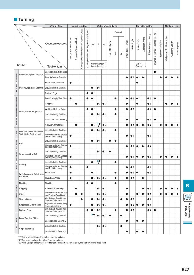
Turning Check Item Insert Grades Cutting Conditions Tool Geometry Setting Machine Change to More Thermal Shock Resistant Grade Change to More Welding Resistant Grade Coolant G) Change to Harder Grade Change to Tougher Grade Approach Angle Edge Strength / Honing Change to Higher Tolerance (M→ Workpiece / Tool Installation Countermeasures Vc f ap Tool Path Review Chipbreaker Review Rake Angle Corner-R(rε) Toolholder Rigidity Overhang Length Power, Rigidity Wet Dry Trouble Higher (Larger)↑ Larger ↑ Trouble Item Lower (Smaller)↓ Smaller ↓ Unsuitable Insert Tolerance ● Unstable Dimension Unstable Workpiece Dimension Tool and Workpiece Evacuation ● ●↑ ●↓ ●↓ ● ● ● ● Flank Wear Increase ● ●↑ Frequent Offset during Machining Unsuitable Cutting Conditions ●↓ ●↑ Built-up Edge ● ●↑ Surface roughness deterioration Poor Cutting by Tool Wear ● ● ●↓ ● ● ●↑ ●↑ ●↓ ● Chipping ● ●↓ ●↓ ● ●↑ ●↑ ● ● ● Welding, Built-up Edge ● ●↑ ● ● ●↑ ●↓ ● Poor Surface Roughness Unsuitable Cutting Conditions ●↑ ●↓ ●↓ ● Unsuitable Tool Geometry ● ●↑ ●↓ ● Vibration, Chattering ● ●↓ *1● ●↓ ● ●↑ ●↓ ●↓ ●↓ ● ● ● ● ↓ Heat Deterioration of Accuracy or Unsuitable Cutting Conditions ●↓ ●↓ ●↓ ● Tool Life by Cutting Heat Unsuitable Insert Grades ● ● ●↑ ●↓ and Tool Geometry Burr, Workpiece Chip Off and Scuffing Unsuitable Cutting Conditions ●↓ ●↑ ● ● Burr Unsuitable Insert Grades and Tool Geometry ● ● ●↑ ●↓ ●↓ ●↓ Unsuitable Cutting Conditions ●↓ ●↓ ● Workpiece Chip Off Unsuitable Insert Grades and Tool Geometry ● ● ●↑ ●↑ ●↑ ●↓ ● ● ● ● Unsuitable Cutting Conditions ●↑ *2● ● Scuffing ↓ Unsuitable Insert Grades ● ● ● ●↑ ●↓ and Tool Geometry Wear Increase at Relief Face, Flank Wear ● ●↓ ● ● ●↑ ●↑ ●↓ Rake Face Rake Face Wear ● ●↓ ●↓ ●↓ ● ● ●↑ ●↑ Notching Notching ● ●↓ ● R Edge Damage Chipping Vibration, Chattering ● ●↓ ●↓ ● ●↑ ●↑ ● ● ● ● Crack Unsuitable Insert Grades ● ● ●↓ ●↓ ● ●↑ ●↑ ●↑ ● ● ● ● and Cutting Conditions Vc= π×Dm×n Thermal Crack Work Hardness, Unsuitable Insert ● ●↓ ●↓ ●↓ ● ● ●↑ ●↓ Grades and Cutting Conditions Edge Nose Deformation Edge Nose Deformation during ● ●↓ ●↓ ●↓ ● ●↓ ●↑ ●↑ ●↑ Information Interrupted machining Technical Built-up Edge Work Hardness, Unsuitable Insert ● ●↑ ●↑ ● ● ●↑ ●↓ ● Grades and Cutting Conditions Unsuitable Cutting Conditions *3● ●↑ ●↑ ● ● Long, Tangling Chips ↓ Chip Control Unsuitable Tool Geometry ● ●↓ ●↓ Unsuitable Cutting Conditions ●↓ ●↓ ● Chips scattering Unsuitable Tool Geometry ● ●↑ ●↑ *1) To prevent chattering, the higher f may be suitable. *2) To prevent scuffing, the higher f may be suitable. *3) When using X-chipbreaker insert for soft steel and low carbon steel, the higher Vc cuts chips short. R27