Основной каталог Kyocera 2016-2017 - страница 880
Навигация
 Каталог Kyocera фрезы MFH для высокоскоростной обработки
 Каталог Kyocera фрезы MEC высокопроизводительные концевые и торцевые фрезы
 Каталог микроинструмента Kyocera 2015-2016
 Каталог Kyocera высокоэффективные сверла со сменными пластинами DRV
 Каталог Kyocera пластины TQ для нарезания резьбы c прессованным стружколомом
 Каталог Kyocera высокопроизводительные модульные сверла DRA
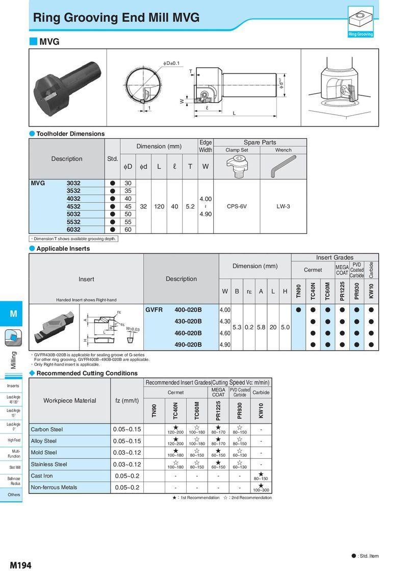
Ring Grooving End Mill MVG Ring Grooving ■ MVG φ D±0.1 T φ d h7 W 1 ℓ L ● Toolholder Dimensions Dimension (mm) Edge Spare Parts Width Clamp Set Wrench Description Std. φD φd L ℓ T W MVG 3032 ● 30 3532 ● 35 4032 ● 40 4.00 4532 ● 45 32 120 40 5.2 ~ CPS-6V LW-3 5032 ● 50 4.90 5532 ● 55 6032 ● 60 ・Dimension T shows available grooving depth. ● Applicable Inserts Insert Grades Dimension (mm) MEGA PVD Carbide Cermet COAT Coated Insert Description Carbide W B rε A L H TN90 TC40N TC60M PR1225 PR930 KW10 Handed Insert shows Right-hand M rε GVFR 400-020B 4.00 ● ● ● ● ● ● A 430-020B 4.30 ● ● ● ● ● 2゜ rε W±0.03 5.3 0.2 5.8 20 5.0 B L 460-020B 4.60 ● ● ● ● ● H 490-020B 4.90 ● ● ● ● ● Milling ・GVFR430B-020B is applicable for sealing groove of G-series For other ring grooving, GVFR400B~490B-020B are applicable. ・Only Right-hand insert is applicable. ◆ Recommended Cutting Conditions Inserts Recommended Insert Grades(Cutting Speed Vc: m/min) Cermet MEGA PVD Coated Carbide Lead Angle COAT Carbide 45°/20° Workpiece Material fz (mm/t) TC40N TC60M PR1225 PR930 KW10 Lead Angle TN90 15° Lead Angle ★ ☆ ★ ☆ 0° Carbon Steel 0.05~0.15 120~200 100~180 80~170 80~150 - High Feed Alloy Steel 0.05~0.15 ★ ☆ ★ ☆ - 120~200 100~180 80~170 80~150 Multi- Mold Steel 0.03~0.12 ★ ☆ ★ ☆ - Function 100~180 80~150 60~150 60~130 Stainless Steel 0.03~0.12 ☆ ☆ ★ ☆ - Slot Mill 100~180 80~150 60~150 60~130 Cast Iron 0.05~0.2 - - - - ★ Ball-nose 80~150 Radius Non-ferrous Metals 0.05~0.2 - - - - ★ 100~300 Others ★:1st Recommendation ☆:2nd Recommendation ● : Std. Item M194