Основной каталог Kyocera 2016-2017 - страница 878
Навигация
 Каталог Kyocera фрезы MFH для высокоскоростной обработки
 Каталог Kyocera фрезы MEC высокопроизводительные концевые и торцевые фрезы
 Каталог микроинструмента Kyocera 2015-2016
 Каталог Kyocera высокоэффективные сверла со сменными пластинами DRV
 Каталог Kyocera пластины TQ для нарезания резьбы c прессованным стружколомом
 Каталог Kyocera высокопроизводительные модульные сверла DRA
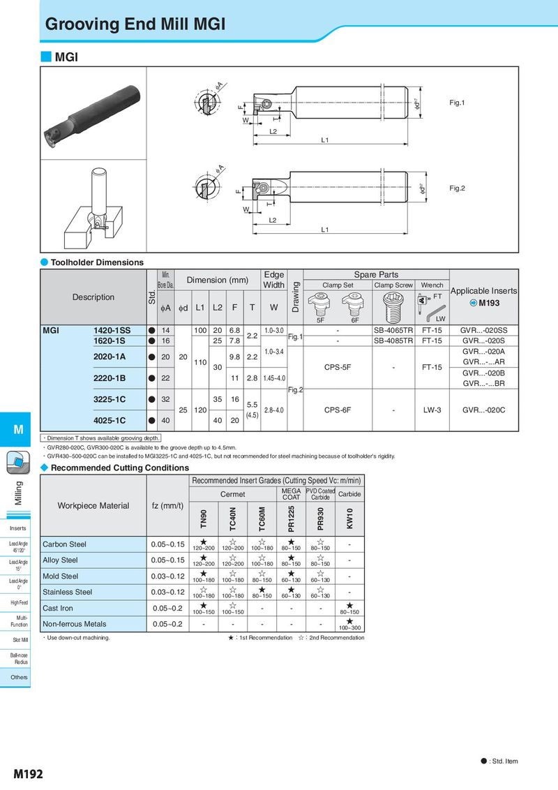
Grooving End Mill MGI ■ MGI φA F φdh7 Fig.1 W T L2 L1 φA F φdh7 Fig.2 T W L2 L1 ● Toolholder Dimensions Min. Dimension (mm) Edge Spare Parts Bore Dia. Width Drawing Clamp Set Clamp Screw Wrench Applicable Inserts Description Std. FT φA φd L1 L2 F T W M193 5F 6F LW MGI 1420-1SS ● 14 100 20 6.8 2.2 1.0~3.0 Fig.1 - SB-4065TR FT-15 GVR...-020SS 1620-1S ● 16 25 7.8 - SB-4085TR FT-15 GVR...-020S 2020-1A ● 20 20 9.8 2.2 1.0~3.4 GVR...-020A 110 30 CPS-5F - FT-15 GVR...-...AR 2220-1B ● 22 11 2.8 1.45~4.0 GVR...-020B Fig.2 GVR...-...BR 3225-1C ● 32 35 16 5.5 25 120 (4.5) 2.8~4.0 CPS-6F - LW-3 GVR...-020C 4025-1C ● 40 40 20 M ・Dimension T shows available grooving depth. ・GVR280-020C, GVR300-020C is available to the groove depth up to 4.5mm. ・GVR430~500-020C can be installed to MGI3225-1C and 4025-1C, but not recommended for steel machining because of toolholder's rigidity. ◆ Recommended Cutting Conditions Milling Recommended Insert Grades (Cutting Speed Vc: m/min) Cermet MEGA PVD Coated Carbide COAT Carbide Workpiece Material fz (mm/t) TC40N TC60M PR1225 PR930 KW10 Inserts TN90 Lead Angle Carbon Steel 0.05~0.15 ★ ☆ ☆ ★ ☆ - 45°/20° 120~200 120~200 100~180 80~150 80~150 Lead Angle Alloy Steel 0.05~0.15 ★ ☆ ☆ ★ ☆ - 15° 120~200 120~200 100~180 80~150 80~150 Mold Steel 0.03~0.12 ★ ☆ ☆ ★ ☆ - Lead Angle 100~180 100~180 80~150 60~130 60~130 0° Stainless Steel 0.03~0.12 ☆ ☆ ★ ★ ☆ - 100~180 100~180 80~150 60~130 60~130 High Feed Cast Iron 0.05~0.2 ★ ☆ - - - ★ 100~150 100~150 80~150 Multi- ★ Function Non-ferrous Metals 0.05~0.2 - - - - - 100~300 Slot Mill ・Use down-cut machining. ★:1st Recommendation ☆:2nd Recommendation Ball-nose Radius Others ● : Std. Item M192