Основной каталог Kyocera 2016-2017 - страница 857
Навигация
 Каталог Kyocera фрезы MFH для высокоскоростной обработки
 Каталог Kyocera фрезы MEC высокопроизводительные концевые и торцевые фрезы
 Каталог микроинструмента Kyocera 2015-2016
 Каталог Kyocera высокоэффективные сверла со сменными пластинами DRV
 Каталог Kyocera пластины TQ для нарезания резьбы c прессованным стружколомом
 Каталог Kyocera высокопроизводительные модульные сверла DRA
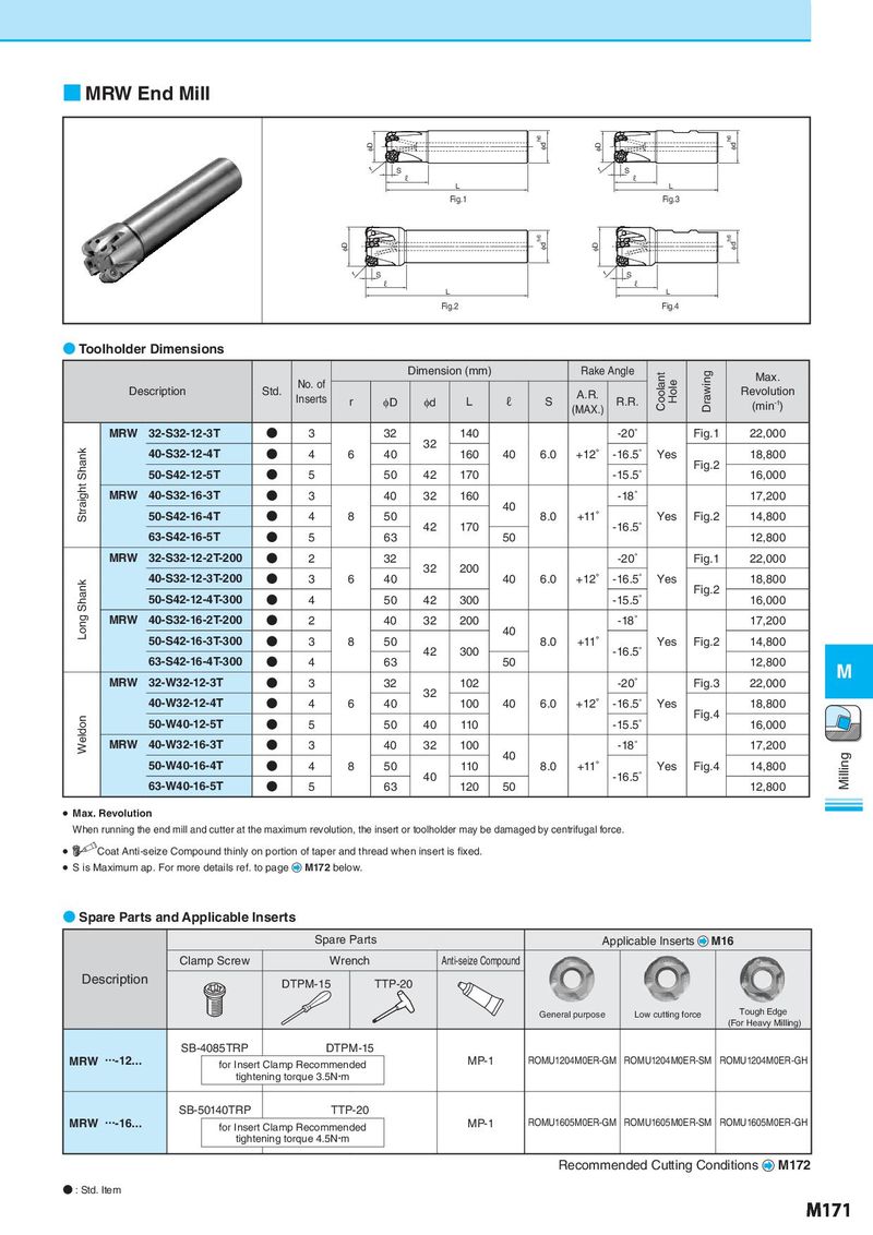
■ MRW End Mill φD φd h6 φD φdh6 r S r S ℓ ℓ L L Fig.1 Fig.3 φD φd h6 φD φdh6 r S r S ℓ ℓ L L Fig.2 Fig.4 ● Toolholder Dimensions Dimension (mm) Rake Angle Coolant Drawing Max. Description Std. No. of Hole Revolution Inserts r φD φd L ℓ S A.R. R.R. (min-1) (MAX.) MRW 32-S32-12-3T ● 3 32 140 -20° Fig.1 22,000 Straight Shank 40-S32-12-4T ● 4 6 40 32 160 40 6.0 +12° -16.5° Yes 18,800 50-S42-12-5T ● 5 50 42 170 -15.5° Fig.2 16,000 MRW 40-S32-16-3T ● 3 40 32 160 -18° 17,200 50-S42-16-4T ● 4 8 50 40 8.0 +11° Yes Fig.2 14,800 63-S42-16-5T ● 5 63 42 170 50 -16.5° 12,800 MRW 32-S32-12-2T-200 ● 2 32 -20° Fig.1 22,000 40-S32-12-3T-200 ● 3 6 40 32 200 40 6.0 +12° -16.5° Yes 18,800 Long Shank 50-S42-12-4T-300 ● 4 50 42 300 -15.5° Fig.2 16,000 MRW 40-S32-16-2T-200 ● 2 40 32 200 -18° 17,200 50-S42-16-3T-300 ● 3 8 50 40 8.0 +11° Yes Fig.2 14,800 63-S42-16-4T-300 ● 4 63 42 300 50 -16.5° 12,800 MRW 32-W32-12-3T ● 3 32 102 -20° Fig.3 22,000 M 40-W32-12-4T ● 4 6 40 32 100 40 6.0 +12° -16.5° Yes 18,800 Weldon 50-W40-12-5T ● 5 50 40 110 -15.5° Fig.4 16,000 MRW 40-W32-16-3T ● 3 40 32 100 -18° 17,200 50-W40-16-4T ● 4 8 50 110 40 8.0 +11° Yes Fig.4 14,800 Milling 63-W40-16-5T ● 5 63 40 120 50 -16.5° 12,800 ● Max. Revolution When running the end mill and cutter at the maximum revolution, the insert or toolholder may be damaged by centrifugal force. ● Coat Anti-seize Compound thinly on portion of taper and thread when insert is fixed. S ● is Maximum ap. For more details ref. to page M172 below. ● Spare Parts and Applicable Inserts Spare Parts Applicable Inserts M16 Clamp Screw Wrench Anti-seize Compound Description DTPM-15 TTP-20 General purpose Low cutting force Tough Edge (For Heavy Milling) SB-4085TRP DTPM-15 MRW ・・・-12... for Insert Clamp Recommended MP-1 ROMU1204M0ER-GM ROMU1204M0ER-SM ROMU1204M0ER-GH tightening torque 3.5N・m SB-50140TRP TTP-20 MRW ・・・-16... for Insert Clamp Recommended MP-1 ROMU1605M0ER-GM ROMU1605M0ER-SM ROMU1605M0ER-GH tightening torque 4.5N・m Recommended Cutting Conditions M172 ● : Std. Item M171