Основной каталог Kyocera 2016-2017 - страница 824
Навигация
 Каталог Kyocera фрезы MFH для высокоскоростной обработки
 Каталог Kyocera фрезы MEC высокопроизводительные концевые и торцевые фрезы
 Каталог микроинструмента Kyocera 2015-2016
 Каталог Kyocera высокоэффективные сверла со сменными пластинами DRV
 Каталог Kyocera пластины TQ для нарезания резьбы c прессованным стружколомом
 Каталог Kyocera высокопроизводительные модульные сверла DRA
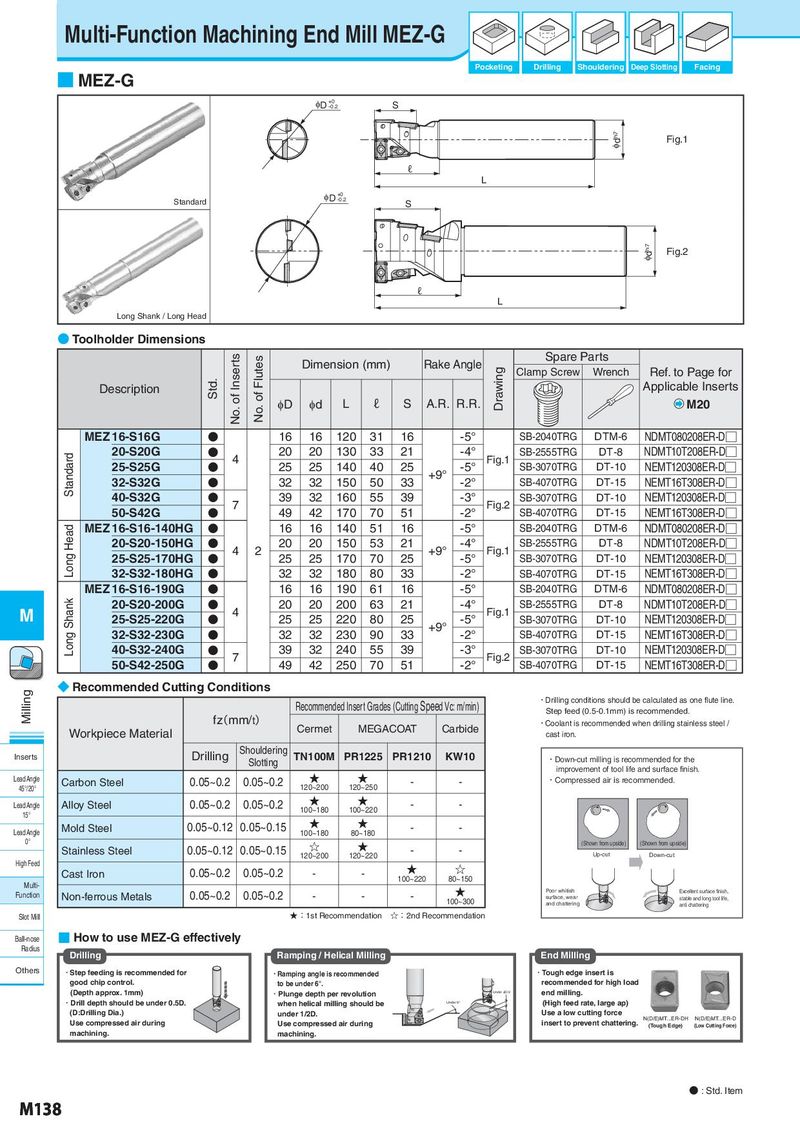
Multi-Function Machining End Mill MEZ-G Pocketing Drilling Shouldering Deep Slotting Facing ■ MEZ-G φD +0 S -0.2 φdh7 Fig.1 ℓ L φD +0 Standard -0.2 S φdh7 Fig.2 ℓ L Long Shank / Long Head ● Toolholder Dimensions No. of Inserts No. of Flutes Dimension (mm) Rake Angle Spare Parts Drawing Clamp Screw Wrench Ref. to Page for Description Std. Applicable Inserts φD φd L ℓ S A.R. R.R. M20 MEZ 16-S16G ● 16 16 120 31 16 -5° SB-2040TRG DTM-6 NDMT080208ER-D□ Standard 20-S20G ● 4 20 20 130 33 21 -4° Fig.1 SB-2555TRG DT-8 NDMT10T208ER-D□ 25-S25G ● 25 25 140 40 25 +9° -5° SB-3070TRG DT-10 NEMT120308ER-D□ 32-S32G ● 32 32 150 50 33 -2° SB-4070TRG DT-15 NEMT16T308ER-D□ 40-S32G ● 7 39 32 160 55 39 -3° Fig.2 SB-3070TRG DT-10 NEMT120308ER-D□ 50-S42G ● 49 42 170 70 51 -2° SB-4070TRG DT-15 NEMT16T308ER-D□ Long Head MEZ 16-S16-140HG ● 16 16 140 51 16 -5° SB-2040TRG DTM-6 NDMT080208ER-D□ 20-S20-150HG ● 4 2 20 20 150 53 21 +9° -4° Fig.1 SB-2555TRG DT-8 NDMT10T208ER-D□ 25-S25-170HG ● 25 25 170 70 25 -5° SB-3070TRG DT-10 NEMT120308ER-D□ 32-S32-180HG ● 32 32 180 80 33 -2° SB-4070TRG DT-15 NEMT16T308ER-D□ MEZ 16-S16-190G ● 16 16 190 61 16 -5° SB-2040TRG DTM-6 NDMT080208ER-D□ M Long Shank 20-S20-200G ● 4 20 20 200 63 21 -4° Fig.1 SB-2555TRG DT-8 NDMT10T208ER-D□ 25-S25-220G ● 25 25 220 80 25 +9° -5° SB-3070TRG DT-10 NEMT120308ER-D□ 32-S32-230G ● 32 32 230 90 33 -2° SB-4070TRG DT-15 NEMT16T308ER-D□ 40-S32-240G ● 7 39 32 240 55 39 -3° Fig.2 SB-3070TRG DT-10 NEMT120308ER-D□ 50-S42-250G ● 49 42 250 70 51 -2° SB-4070TRG DT-15 NEMT16T308ER-D□ Milling ◆ Recommended Cutting Conditions Recommended Insert Grades (Cutting Speed Vc: m/min) ・Drilling conditions should be calculated as one flute line. Step feed (0.5-0.1mm) is recommended. fz(mm/t) Cermet MEGACOAT Carbide ・Coolant is recommended when drilling stainless steel / Workpiece Material cast iron. Inserts Drilling Shouldering TN100M PR1225 PR1210 KW10 ・Down-cut milling is recommended for the Slotting improvement of tool life and surface finish. Lead Angle Carbon Steel 0.05~0.2 0.05~0.2 ★ ★ - - ・Compressed air is recommended. 45°/20° 120~200 120~250 Lead Angle Alloy Steel 0.05~0.2 0.05~0.2 ★ ★ - - 15° 100~180 100~220 Lead Angle Mold Steel 0.05~0.12 0.05~0.15 ★ ★ - - 100~180 80~180 0° 0.05~0.12 0.05~0.15 ☆ ★ (Shown from upside) (Shown from upside) Stainless Steel 120~200 120~220 - - Up-cut Down-cut High Feed ★ ☆ Cast Iron 0.05~0.2 0.05~0.2 - - 100~220 80~150 Multi- ★ Poor whitish Excellent surface finish, Function Non-ferrous Metals 0.05~0.2 0.05~0.2 - - - 100~300 surface, wear stable and long tool life, and chattering anti chattering Slot Mill ★:1st Recommendation ☆:2nd Recommendation Ball-nose ■ How to use MEZ-G effectively Radius Drilling Ramping / Helical Milling End Milling Others ・Step feeding is recommended for ・Ramping angle is recommended ・Tough edge insert is good chip control. to be under 6°. recommended for high load (Depth approx. 1mm) ・Plunge depth per revolution Under φD/2 end milling. ・Drill depth should be under 0.5D. when helical milling should be Under 6° (High feed rate, large ap) (D:Drilling Dia.) under 1/2D. Use a low cutting force N(D/E)MT...ER-DH N(D/E)MT...ER-D Use compressed air during Use compressed air during insert to prevent chattering. (Tough Edge) (Low Cutting Force) machining. machining. ● : Std. Item M138