Основной каталог Kyocera 2016-2017 - страница 808
Навигация
 Каталог Kyocera фрезы MFH для высокоскоростной обработки
 Каталог Kyocera фрезы MEC высокопроизводительные концевые и торцевые фрезы
 Каталог микроинструмента Kyocera 2015-2016
 Каталог Kyocera высокоэффективные сверла со сменными пластинами DRV
 Каталог Kyocera пластины TQ для нарезания резьбы c прессованным стружколомом
 Каталог Kyocera высокопроизводительные модульные сверла DRA
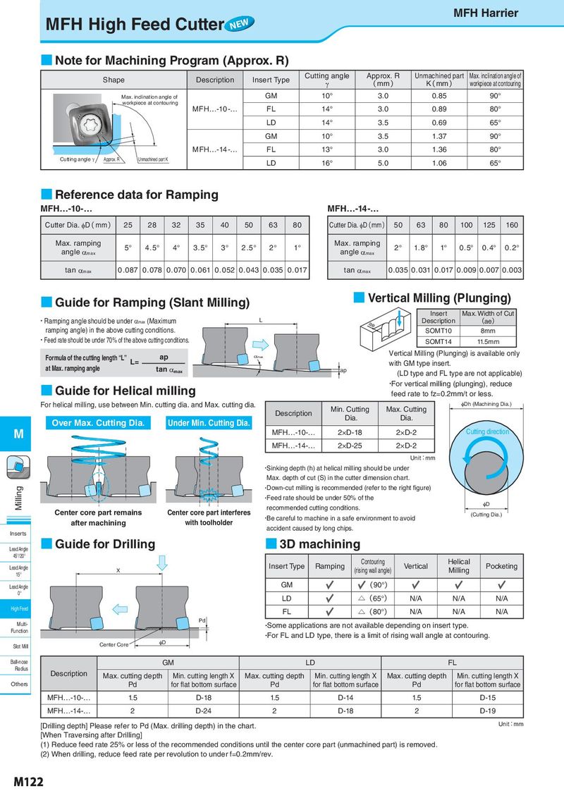
MFH High Feed Cutter NEW MFH Harrier ■ Note for Machining Program (Approx. R) Shape Description Insert Type Cutting angle Approx. R Unmachined part Max. inclination angle of γ ( mm ) K( mm ) workpiece at contouring Max. inclination angle of GM 10° 3.0 0.85 90° workpiece at contouring MFH…-10 -… FL 14° 3.0 0.89 80° LD 14° 3.5 0.69 65° GM 10° 3.5 1.37 90° MFH…-14 -… FL 13° 3.0 1.36 80° Cutting angle a Approx. R Unmachined part K LD 16° 5.0 1.06 65° ■ Reference data for Ramping MFH…-10-… MFH…-14-… Cutter Dia. φD( mm) 25 28 32 35 40 50 63 80 Cutter Dia. φD(mm) 50 63 80 100 125 160 Max. ramping 5° 4 . 5° 4° 3 . 5° 3° 2 . 5° 2° 1° Max. ramping 2° 1.8° 1° 0.5° 0.4° 0.2° angle αmax angle αmax tan αmax 0.087 0.078 0.070 0 . 0 61 0.052 0.043 0.035 0 . 017 tan αmax 0.035 0.031 0.017 0.009 0.007 0.003 ■ Guide for Ramping (Slant Milling) ■ Vertical Milling (Plunging) Insert Max. Width of Cut ・Ramping angle should be under αmax (Maximum L ae Description (ae) ramping angle) in the above cutting conditions. SOMT10 8mm ・Feed rate should be under 70% of the above cutting conditions. SOMT14 11.5mm Formula of the cutting length “L” L= ap _ max Vertical Milling (Plunging) is available only at Max. ramping angle tan αmax with GM type insert. ap (LD type and FL type are not applicable) ■ Guide for Helical milling ・For vertical milling (plunging), reduce feed rate to fz=0.2mm/t or less. For helical milling, use between Min. cutting dia. and Max. cutting dia. Min. Cutting Max. Cutting qDh (Machining Dia.) Description Dia. Dia. Over Max. Cutting Dia. Under Min. Cutting Dia. M MFH…-10-… 2×D-18 2×D-2 Cutting direction MFH…-14-… 2×D-25 2×D-2 Unit:mm ・Sinking depth (h) at helical milling should be under Max. depth of cut (S) in the cutter dimension chart. Milling ・Down-cut milling is recommended (refer to the right figure) ・Feed rate should be under 50% of the recommended cutting conditions. qD Center core part remains Center core part interferes ・Be careful to machine in a safe environment to avoid (Cutting Dia.) after machining with toolholder accident caused by long chips. Inserts Lead Angle ■ Guide for Drilling ■ 3D machining 45°/20° Insert Type Ramping Contouring Vertical Helical Pocketing Lead Angle X (rising wall angle) Milling 15° Lead Angle GM (90°) 0° LD △(65°) N/A N/A N/A High Feed FL △(80°) N/A N/A N/A Multi- Pd ・Some applications are not available depending on insert type. Function ・For FL and LD type, there is a limit of rising wall angle at contouring. Slot Mill Center Core qD Ball-nose GM LD FL Radius Description Max. cutting depth Min. cutting length X Max. cutting depth Min. cutting length X Max. cutting depth Min. cutting length X Others Pd for flat bottom surface Pd for flat bottom surface Pd for flat bottom surface MFH…-10-… 1.5 D-18 1.5 D-14 1.5 D-15 MFH…-14-… 2 D-24 2 D-18 2 D-19 [Drilling depth] Please refer to Pd (Max. drilling depth) in the chart. Unit:mm [When Traversing after Drilling] (1) Reduce feed rate 25% or less of the recommended conditions until the center core part (unmachined part) is removed. (2) When drilling, reduce feed rate per revolution to under f=0.2mm/rev. M122