Основной каталог Kyocera 2016-2017 - страница 797
Навигация
 Каталог Kyocera фрезы MFH для высокоскоростной обработки
 Каталог Kyocera фрезы MEC высокопроизводительные концевые и торцевые фрезы
 Каталог микроинструмента Kyocera 2015-2016
 Каталог Kyocera высокоэффективные сверла со сменными пластинами DRV
 Каталог Kyocera пластины TQ для нарезания резьбы c прессованным стружколомом
 Каталог Kyocera высокопроизводительные модульные сверла DRA
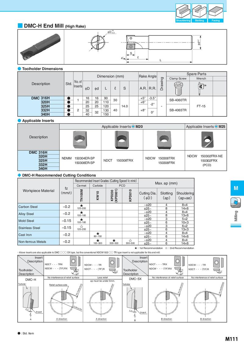
Shouldering Slotting Facing ■ DMC-H End Mill (High Rake) φD+−00.2 φd h7 S 4° ℓ L ● Toolholder Dimensions Dimension (mm) Rake Angle Spare Parts Drawing Clamp Screw Wrench Description Std. No. of Inserts φD φd L ℓ S A.R. R.R. DMC 316H ● 1 16 16 90 30 +5° -3.5° SB-4060TR 320H ● 20 20 110 +6° -2° 325H ● 25 25 120 14.0 - FT-15 332H ● 2 32 32 130 40 +8° 0° SB-4065TR 340H ● 40 150 ● Applicable Inserts Applicable Inserts M20 Applicable Inserts M25 Description DMC 316H 320H NDMM 150304ER-SP NDCW 150308TRX NDCW 150302FRX-NE 325H 150308ER-SP NDCT 150308TRX 150308FRX 150302FRX 332H (PCD) 340H ◆ DMC-H Recommended Cutting Conditions Recommended Insert Grades (Cutting Speed Vc: m/min) Max. ap (mm) fz Cermet Carbide PCD M Workpiece Material (mm/t) TN100M KW10 KPD230 (KPD001) KPD010 Cutting Dia. Slotting Shouldering ( φD ) (ap) (ap×ae) Carbon Steel ~0.2 ★ ~φ20 4 8×4 120~200 φ25~ 8 14×6 Alloy Steel ~0.2 ★ ~φ20 4 8×4 Milling 100~180 φ25~ 8 13×6 Mold Steel ~0.15 ★ ~φ20 3 5×2 100~180 φ25~ 6 10×3 Stainless Steel ~0.15 ☆ ~φ20 3 6×2 120~200 φ25~ 6 13×3 Cast Iron ~0.2 ★ ~φ20 4 8×4 80~150 φ25~ 6 14×6 Non-ferrous Metals ~0.2 ★ ★ ☆ ~φ20 4 8×4 100~300 300~500 300~500 φ25~ 6 14×6 ★:1st Recommendation ☆:2nd Recommendation ・Above inserts are also applicable to DMC ○○○ SX type, but the conventional NDCW1503 ○○ TR type insert is not applicable for this end mill. Insert Insert Description Description NDCT・・・TRX NDCW・・・TR NDCT・・・TRX NDCW・・・TR Toolholder NDCW・・・(T/F)RX 15° NDCT・・・(T/F)R Toolholder NDCW・・・(T/F)RX 15° NDCT・・・(T/F)R 15° 15° Description 30° Description 30° DMC-H No interference of relief surface Less relief DMC-SX No interference of relief surface No interference of relief surface ap must be under 5mm. Toolholder Relief surface side No interference Less relief Toolholder No interference No interference A.R. Cutting Dia. A.R. Insert Insert A A direction A direction B B direction B direction ● : Std. Item M111