Основной каталог Kyocera 2016-2017 - страница 750
Навигация
 Каталог Kyocera фрезы MFH для высокоскоростной обработки
 Каталог Kyocera фрезы MEC высокопроизводительные концевые и торцевые фрезы
 Каталог микроинструмента Kyocera 2015-2016
 Каталог Kyocera высокоэффективные сверла со сменными пластинами DRV
 Каталог Kyocera пластины TQ для нарезания резьбы c прессованным стружколомом
 Каталог Kyocera высокопроизводительные модульные сверла DRA
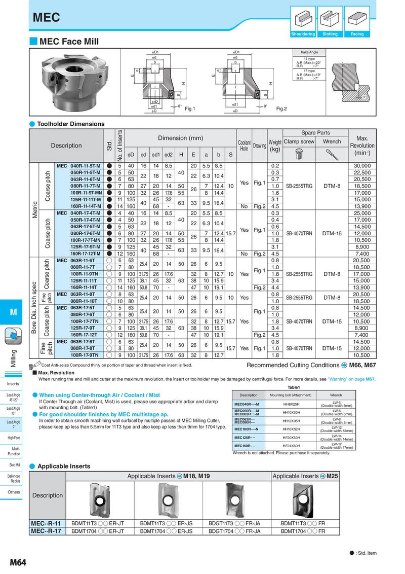
MEC Shouldering Slotting Facing ■ MEC Face Mill φD1 φD1 Rake Angle φd φd 11 type b b A.R.(Max.):+23° R.R. :-7° a a 17 type E E A.R.(Max.):+19° R.R. :-7° H H S S 0° φd2 φd1 φd1 0° Fig.1 0° Fig.2 φD φD ● Toolholder Dimensions No. of Inserts Spare Parts Std. Dimension (mm) Coolant Weight Clamp screw Wrench Max. Description Hole Drawing (kg) Revolution ϕD ϕd ϕd1 ϕd2 H E a b S (min-1) MEC 040R-11-5T-M N 5 40 16 14 8.5 20 5.5 8.5 0.2 30,000 Coarse pitch 050R-11-5T-M N 5 50 22 18 12 40 22 6.3 10.4 0.3 22,500 063R-11-6T-M N 6 63 Yes Fig.1 0.7 20,500 080R-11-7T-M N 7 80 27 20 14 50 26 7 12.4 10 1.0 SB-2555TRG DTM-8 18,500 100R-11-9T-MN N 9 100 32 26 17.6 55 8 14.4 1.6 17,000 Metric 125R-11-11T-M N 11 125 40 45 32 63 33 9.5 16.4 3.1 15,000 160R-11-14T-M N 14 160 68 - No Fig.2 4.5 13,900 MEC 040R-17-4T-M N 4 40 16 14 8.5 20 5.5 8.5 0.3 25,000 Coarse pitch 050R-17-4T-M N 4 50 22 18 12 40 22 6.3 10.4 0.4 17,000 063R-17-5T-M N 5 63 Yes Fig.1 0.6 14,500 080R-17-6T-M N 6 80 27 20 14 50 26 7 12.4 15.7 1.0 SB-4070TRN DTM-15 12,000 100R-17-7T-MN N 7 100 32 26 17.6 55 8 14.4 1.8 10,500 125R-17-9T-M N 9 125 40 45 32 63 33 9.5 16.4 3.1 8,900 160R-17-12T-M N 12 160 68 - No Fig.2 4.5 7,400 Coarse pitch MEC 063R-11-6T ○ 6 63 25.4 20 14 50 26 6 9.5 0.8 20,500 080R-11-7T ○ 7 80 Fig.1 1.0 18,500 100R-11-9TN ○ 9 100 31.75 26 17.6 32 8 12.7 10 Yes 1.8 SB-2555TRG DTM-8 17,000 Bore Dia. Inch spec 125R-11-11T ○ 11 125 38.1 45 32 63 38 10 15.9 3.4 15,000 160R-11-14T ○ 14 160 50.8 70 - 47 10 19.1 Fig.2 4.4 13,900 Fine pitch MEC 063R-11-8T ○ 8 63 25.4 20 14 50 26 6 9.5 10 Yes 0.8 SB-2555TRG DTM-8 20,500 080R-11-10T ○ 10 80 1.0 18,500 M Coarse pitch MEC 063R-17-5T ○ 5 63 25.4 20 14 50 26 6 9.5 Fig.1 0.8 14,500 080R-17-6T ○ 6 80 1.0 12,000 100R-17-7TN ○ 7 100 31.75 26 17.6 32 8 12.7 15.7 Yes 1.8 SB-4070TRN DTM-15 10,500 125R-17-9T ○ 9 125 38.1 45 32 63 38 10 15.9 3.4 8,900 160R-17-12T ○ 12 160 50.8 70 - 47 10 19.1 Fig.2 4.5 7,400 Fine pitch MEC 063R-17-6T ○ 6 63 25.4 20 14 50 26 6 9.5 0.8 14,500 Milling 080R-17-8T ○ 8 80 15.7 Yes Fig.1 1.0 SB-4070TRN DTM-15 12,000 100R-17-9TN ○ 9 100 31.75 26 17.6 63 32 8 12.7 1.8 10,500 Coat Anti-seize Compound thinly on portion of taper and thread when insert is fixed. Recommended Cutting Conditions M66, M67 ■ Max. Revolution When running the end mill and cutter at the maximum revolution, the insert or toolholder may be damaged by centrifugal force. For more details, see "Warning" on page M67. Inserts Table1 Lead Angle ● When using Center-through Air / Coolant / Mist Description Mounting bolt (Attachment) Wrench 45°/20° If Center Through air (Coolant, Mist) is used, please use appropriate arbor and clamp LW-5 with mounting bolt. (Table1) MEC040R・・・・-M HH8X25H (Double width 5mm) Lead Angle MEC050R・・・・-M LW-6 15° ● For good shoulder finishes by MEC multistage ap. MEC063R・・・・-M HH10X30H (Double width 6mm) Lead Angle In order to obtain smooth machining wall surfacel by multiple passes of MEC Milling Cutter, MEC063R・・・・ HH12X35H LW-8 MEC080R・・・・ (Double width 8mm) 0° please keep ap less than 5.5mm for 11T3 type and also keep ap less than 9mm for 1704 type. MEC100R・・・・-N HH16X52H LW-12 (Double width 12mm) High Feed MEC125R・・・・ HF20X53H LW-14 (Double width 14mm) MEC160R・・・・ HF24X60H LW-17 Multi- (Double width 17mm) Function Wrench is not attached. Please purchase it separately. Slot Mill ● Applicable Inserts Ball-nose Applicable Inserts M18, M19 Applicable Inserts M25 Radius Others Description MEC··R-11 BDMT11T3 ○○ ER-JT BDMT11T3 ○○ ER-JS BDGT11T3 ○○ FR-JA BDMT11T3 ○○ FR MEC··R-17 BDMT1704 ○○ ER-JT BDMT1704 ○○ ER-JS BDGT1704 ○○ FR-JA BDMT1704 ○○ FR ● : Std. Item M64