Основной каталог Kyocera 2016-2017 - страница 748
Навигация
 Каталог Kyocera фрезы MFH для высокоскоростной обработки
 Каталог Kyocera фрезы MEC высокопроизводительные концевые и торцевые фрезы
 Каталог микроинструмента Kyocera 2015-2016
 Каталог Kyocera высокоэффективные сверла со сменными пластинами DRV
 Каталог Kyocera пластины TQ для нарезания резьбы c прессованным стружколомом
 Каталог Kyocera высокопроизводительные модульные сверла DRA
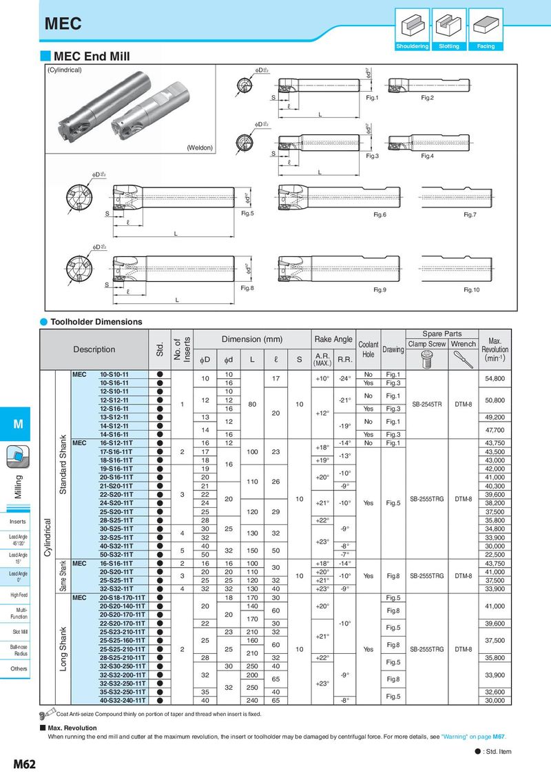
MEC ID +0-0.2 Idh7 Shouldering Slotting Facing ■ MEC End Mill (Cylindrical) ID +0 S Fig.1 Fig.2 Idh7 -0.2 ℓ L ID +0-0.2 Idh7 S Fig.1 Fig.2 ℓ L ID +0 S Fig.3 Fig.4 -0.2 Idh7 ℓ L (Weldon) S Fig.3 Fig.4 ℓ ID +0-0.2 L Idh7 ID +0-0.2 S Fig.5 Fig.6 Fig.7 ℓ Idh7 L D I S +0 Fig.5 Fig.6 Fig.7 -0.2 ℓ L Idh7 ID +0-0.2 S Fig.8 Fig.9 Fig.10 ℓ L Idh7 ● Toolholder S Fig.8 Dimensiℓons Fig.9 Fig.10 L Spare Parts Std. No. of Inserts Dimension (mm) Rake Angle Coolant Clamp Screw Wrench Max. Description A.R. Hole Drawing Revolution φD φd L ℓ S (MAX.) R.R. (min-1) MEC 10-S10-11 N 10 10 17 +10° -24° No Fig.1 54,800 10-S16-11 N 16 Yes Fig.3 12-S10-11 N 10 No Fig.1 12-S12-11 N 1 12 12 80 10 -21° SB-2545TR DTM-8 50,800 12-S16-11 N 16 20 +12° Yes Fig.3 M 13-S12-11 N 13 12 No Fig.1 49,200 14-S12-11 N 14 -19° 47,700 Standard Shank 14-S16-11 N 16 Yes Fig.3 MEC 16-S12-11T N 16 12 +18° -14° No Fig.1 43,750 17-S16-11T N 2 17 100 23 -13° 43,500 18-S16-11T N 18 16 +19° 43,000 19-S16-11T N 19 -10° 42,000 Milling 20-S16-11T N 20 110 26 +20° 41,000 21-S20-11T N 21 -9° 40,300 22-S20-11T N 3 22 20 10 SB-2555TRG DTM-8 39,600 24-S20-11T N 24 +21° -10° Yes Fig.5 38,200 25-S20-11T N 25 120 29 37,500 Inserts Cylindrical 28-S25-11T N 28 +22° 35,800 30-S25-11T N 4 30 25 130 32 -9° 34,800 Lead Angle 32-S25-11T N 32 +23° 33,900 45°/20° 40-S32-11T N 40 -8° 30,000 Lead Angle 50-S32-11T N 5 50 32 150 50 -7° 22,500 15° Same Shank MEC 16-S16-11T N 2 16 16 100 +18° -14° 43,750 20-S20-11T N 20 20 110 30 +20° 41,000 Lead Angle 3 10 -10° Yes Fig.8 SB-2555TRG DTM-8 0° 25-S25-11T N 25 25 120 32 +21° 37,500 32-S32-11T N 4 32 32 130 40 +23° -9° 33,900 High Feed MEC 20-S18-170-11T N 18 170 30 Fig.5 Multi- 20-S20-140-11T N 20 140 60 +20° Fig.8 41,000 Function 20-S20-170-11T N 20 170 22-S20-170-11T N 22 30 -10° Fig.5 39,600 Slot Mill Long Shank 25-S23-210-11T N 23 210 32 +21° 25-S25-160-11T N 25 160 60 Fig.8 37,500 Ball-nose 25-S25-210-11T N 2 25 10 Yes SB-2555TRG DTM-8 Radius 28-S25-210-11T N 28 210 32 +22° 35,800 32-S30-250-11T N 30 250 40 Fig.5 Others 32-S32-200-11T N 32 200 65 -9° Fig.8 33,900 32-S32-250-11T N 32 250 +23° 35-S32-250-11T N 35 40 Fig.5 32,600 40-S32-240-11T N 40 240 65 -8° 30,000 Coat Anti-seize Compound thinly on portion of taper and thread when insert is fixed. ■ Max. Revolution When running the end mill and cutter at the maximum revolution, the insert or toolholder may be damaged by centrifugal force. For more details, see "Warning" on page M67. ● : Std. Item M62