Основной каталог Kyocera 2016-2017 - страница 746
Навигация
 Каталог Kyocera фрезы MFH для высокоскоростной обработки
 Каталог Kyocera фрезы MEC высокопроизводительные концевые и торцевые фрезы
 Каталог микроинструмента Kyocera 2015-2016
 Каталог Kyocera высокоэффективные сверла со сменными пластинами DRV
 Каталог Kyocera пластины TQ для нарезания резьбы c прессованным стружколомом
 Каталог Kyocera высокопроизводительные модульные сверла DRA
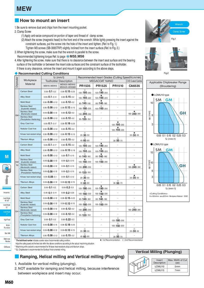
MEW
■ How to mount an insert
Wrench
1. Be sure to remove dust and chips from the insert mounting pocket.
2. Clamp Screw Clamp Screw
(1)Apply anti-seize compound on portion of taper and thread of clamp screw.
(2)Attach the screw (magnetic head) to the front end of the wrench. While lightly pressing the insert against the Fig.1
constraint surfaces, put the screw into the hole of the insert and tighten. (Ref. to Fig. 1.)
Tighten M3 screws (SB-3065TRP) slightly inclined from the insert surface.(Ref. to Fig. 2.) θ
3. When tightening the screw, make sure that the wrench is parallel to the screw. θ
Recommended tightening torque Ref. to page M55,M56
4. After tightening the screw, make sure that there is no clearance between the insert seat surface and the bearing
surface of the toolholder or between the insert side surfaces and the constraint surface of the toolholder.
If there is any clearance, remove the insert and mount it again according to the above steps.
◆ Recommended Cutting Conditions Fig.2
Chipbreaker fz (mm/t) Recommended Insert Grades (Cutting SpeedVc:m/min)
Workpiece Toolholder Description MEGACOAT NANO CVD Coated Carbide Applicable Chipbreaker Range
Material MEW16~MEW18 MEW20~MEW40 PR1535 PR1525 PR1510 CA6535 (Shouldering)
MEW040R~MEW080R
Carbon Steel 0.06~0.1~0.2 0.08~0.15~0.25 ☆ ★ - -
120~180~250 120~180~250 ● LOMU10 type
Alloy Steel 0.06~0.1~0.14 0.08~0.15~0.2 ☆ ★ - -
100~160~220 100~160~220 SM GM
Mold Steel 0.06~0.08~0.12 0.08~0.12~0.2 ☆ ★ - - 10
80~140~180 80~140~180
Stainless Steel 0.06~0.08~0.12 0.08~0.12~0.15 ☆ ☆ - -
(Austenitic related) 100~160~200 100~160~200
Stainless Steel 0.06~0.08~0.12 0.08~0.12~0.2 ☆ - - ★ ap (mm) GH
GM (Martensitic related) 150~200~250 180~240~300 6
Stainless Steel 0.06~0.08~0.12 0.08~0.12~0.2 ★ - - -
(Precipitation Hardening) 90~120~150
Gray Cast Iron 0.06~0.1~0.17 0.08~0.18~0.25 - - ★ -
120~180~250 3
Nodular Cast Iron 0.06~0.08~0.12 0.08~0.15~0.2 - - ★ -
100~150~200
Ni-base heat-resistant alloys 0.06~0.08~0.12 0.08~0.12~0.15 ☆ - - ★
20~30~50 20~30~50 0.05 0.1 0.15 0.2 0.25 0.3
Titanium Alloys 0.06~0.08~0.12 0.08~0.15~0.2 ☆ - ☆ - fz (mm/t)
40~60~80 30~50~70
Carbon Steel 0.06~0.1~0.17 0.08~0.15~0.2 ☆ ★ - - ● LOMU15 type
120~180~250 120~180~250
Alloy Steel 0.06~0.08~0.12 0.08~0.12~0.18 ☆ ★ - - SM GM
100~160~220 100~160~220 15
M Mold Steel 0.06~0.08~0.12 0.08~0.1~0.15 ☆ ★ - -
80~140~180 80~140~180
Stainless Steel 0.06~0.08~0.12 0.08~0.1~0.15 ★ ☆ - - ap (mm)
SM (Austenitic related) 100~160~200 100~160~200 10
*(GL) Stainless Steel 0.06~0.08~0.12 0.08~0.1~0.15 ☆ - - ★ GH
(Martensitic related) 150~200~250 180~240~300
Stainless Steel 0.06~0.08~0.12 0.08~0.1~0.15 ☆ - - - 6
(Precipitation Hardening) 90~120~150
Milling Ni-base heat-resistant alloys 0.06~0.08~0.1 0.08~0.1~0.12 ☆ - - ★ 3
20~30~50 20~30~50
Titanium Alloys 0.06~0.08~0.12 0.08~0.12~0.15 ★ - ☆ -
40~60~80 30~50~70 0.05 0.1 0.15 0.2 0.25 0.3
Carbon Steel 0.06~0.1~0.2 0.08~0.2~0.3 ☆ ★ - -
120~180~250 120~180~250 fz (mm/t)
Inserts Alloy Steel 0.06~0.1~0.14 0.08~0.2~0.25 ☆ ★ - -
100~160~220 100~160~220