Основной каталог Kyocera 2016-2017 - страница 695
Навигация
 Каталог Kyocera фрезы MFH для высокоскоростной обработки
 Каталог Kyocera фрезы MEC высокопроизводительные концевые и торцевые фрезы
 Каталог микроинструмента Kyocera 2015-2016
 Каталог Kyocera высокоэффективные сверла со сменными пластинами DRV
 Каталог Kyocera пластины TQ для нарезания резьбы c прессованным стружколомом
 Каталог Kyocera высокопроизводительные модульные сверла DRA
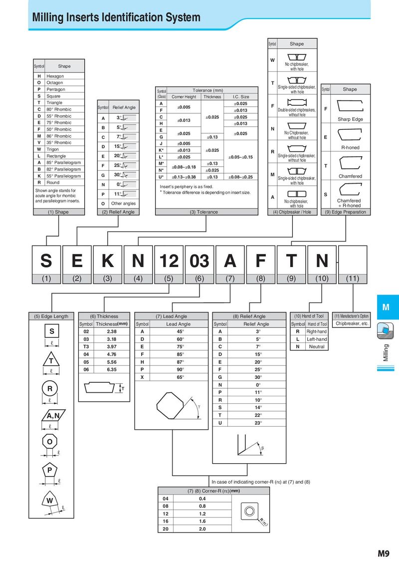
Milling Inserts Identification System Symbol Shape W No chipbreaker, Symbol Shape with hole H Hexagon O Octagon T P Pentagon Tolerance (mm) Single-sided chipbreaker, Symbol Shape Symbol with hole S Square (Class) Corner Height Thickness I.C. Size T Triangle A ±0.025 F C 80° Rhombic Symbol Relief Angle F ±0.005 ±0.013 Double-sided chipbreakers, F D 55° Rhombic A 3° C ±0.025 ±0.025 without hole E 75° Rhombic ±0.013 Sharp Edge 5° H ±0.013 F 50° Rhombic B E N M 86° Rhombic 7° ±0.025 ±0.025 No Chipbreaker, C G ±0.13 without hole E V 35° Rhombic 15° J ±0.005 W Trigon D K* ±0.013 ±0.025 R-honed 20° R Single-sided chipbreaker, L Rectangle E L* ±0.025 ±0.05~±0.15 A 85° Parallelogram M* ±0.13 without hole 82° Parallelogram F 25° ±0.08~±0.18 T B N* ±0.025 K 55° Parallelogram G 30° U* ±0.13~±0.38 ±0.13 ±0.08~±0.25 M Single-sided chipbreaker, Chamfered R Round N 0° with hole Insert's periphery is as fired. Shown angle stands for P 11° * Tolerance difference is depending on insert size. S acute angle for rhombic A and parallelogram inserts. O Other angles No chipbreaker, Chamfered with hole + R-honed (1) Shape (2) Relief Angle (3) Tolerance (4) Chipbreaker / Hole (9) Edge Preparation S E K N 12 03 A F T N (1) (2) (3) (4) (5) (6) (7) (8) (9) (10) (11) M (5) Edge Length (6) Thickness (7) Lead Angle (8) Relief Angle (10) Hand of Tool (11) Manufacturer’s Option Symbol Thickness(mm) Symbol Lead Angle Symbol Relief Angle Symbol Hand of Tool Chipbreaker, etc. S 02 2.38 A 45° A 3° R Right-hand ℓ 03 3.18 D 60° B 5° L Left-hand T3 3.97 E 75° C 7° N Neutral Milling 04 4.76 F 85° D 15° T 05 5.56 H 87° E 20° ℓ 06 6.35 P 90° F 25° X 65° G 30° R T N 0° P 11° ℓ R 10° J S 14° A, N T 22° ℓ U 23° O E ℓ P ℓ In case of indicating corner-R (rH) at (7) and (8) (7) (8) Corner-R (rH)(mm) W 04 0.4 ℓ 08 0.8 12 1.2 16 1.6 R( 20 2.0 rH) M9