Основной каталог Kyocera 2016-2017 - страница 613
Навигация
 Каталог Kyocera фрезы MFH для высокоскоростной обработки
 Каталог Kyocera фрезы MEC высокопроизводительные концевые и торцевые фрезы
 Каталог микроинструмента Kyocera 2015-2016
 Каталог Kyocera высокоэффективные сверла со сменными пластинами DRV
 Каталог Kyocera пластины TQ для нарезания резьбы c прессованным стружколомом
 Каталог Kyocera высокопроизводительные модульные сверла DRA
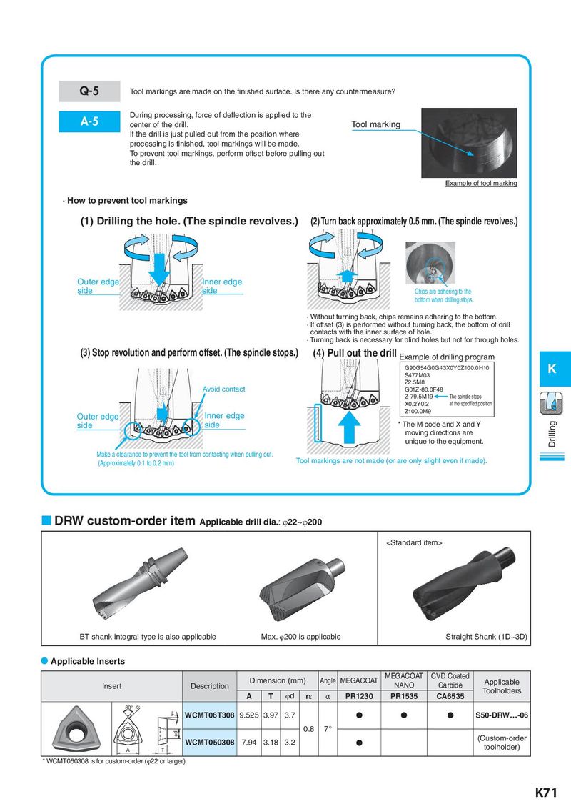
Q-5 Tool markings are made on the finished surface. Is there any countermeasure?
A-5 During processing, force of deflection is applied to the
center of the drill. Tool marking
If the drill is just pulled out from the position where
processing is finished, tool markings will be made.
To prevent tool markings, perform offset before pulling out
the drill.
Example of tool marking
· How to prevent tool markings
(1) Drilling the hole. (The spindle revolves.) (2) Turn back approximately 0.5 mm. (The spindle revolves.)
Outer edge Inner edge
side side Chips are adhering to the
bottom when drilling stops.
· Without turning back, chips remains adhering to the bottom.
· If offset (3) is performed without turning back, the bottom of drill
contacts with the inner surface of hole.
· Turning back is necessary for blind holes but not for through holes.
(3) Stop revolution and perform offset. (The spindle stops.) (4) Pull out the drill Example of drilling program
G90G54G0G43X0Y0Z100.0H10 K
S477M03
Z2.5M8
Avoid contact G01Z -80.0F48
Z-79.5M19 The spindle stops
X0.2Y0.2 at the specified position
Outer edge Inner edge Z100.0M9
side side * The M code and X and Y Drilling
moving directions are
unique to the equipment.
Make a clearance to prevent the tool from contacting when pulling out.
(Approximately 0.1 to 0.2 mm) Tool markings are not made (or are only slight even if made).
DRW custom-order item Applicable drill dia.: φ22~φ200