Основной каталог Kyocera 2016-2017 - страница 585
Навигация
 Каталог Kyocera фрезы MFH для высокоскоростной обработки
 Каталог Kyocera фрезы MEC высокопроизводительные концевые и торцевые фрезы
 Каталог микроинструмента Kyocera 2015-2016
 Каталог Kyocera высокоэффективные сверла со сменными пластинами DRV
 Каталог Kyocera пластины TQ для нарезания резьбы c прессованным стружколомом
 Каталог Kyocera высокопроизводительные модульные сверла DRA
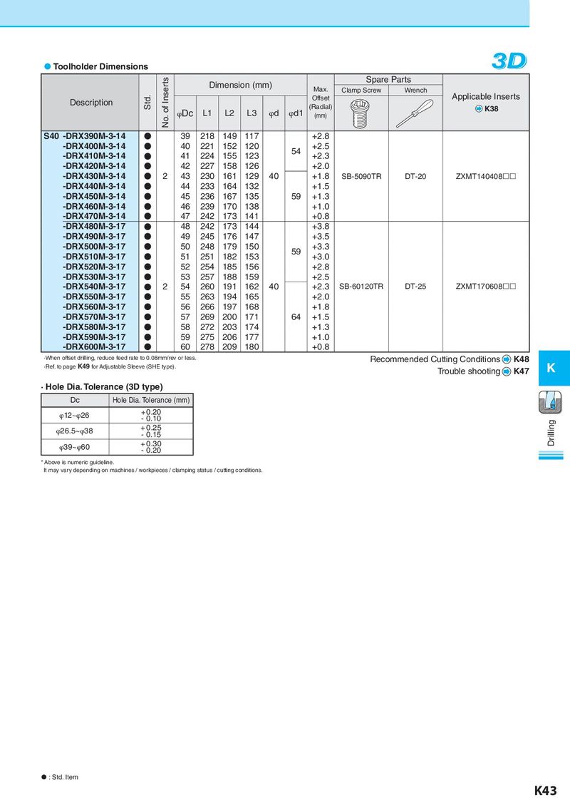
Toolholder Dimensions 3D No. of Inserts Dimension (mm) Spare Parts Max. Clamp Screw Wrench Description Std. Offset Applicable Inserts φDc L1 L2 L3 φd φd1 (Radial) K38 (mm) S40 -DRX390M-3-14 ● 39 218 149 117 +2.8 -DRX400M-3-14 ● 40 221 152 120 54 +2.5 -DRX410M-3-14 ● 41 224 155 123 +2.3 -DRX420M-3-14 ● 42 227 158 126 +2.0 -DRX430M-3-14 ● 2 43 230 161 129 40 +1.8 SB-5090TR DT-20 ZXMT140408 -DRX440M-3-14 ● 44 233 164 132 +1.5 -DRX450M-3-14 ● 45 236 167 135 59 +1.3 -DRX460M-3-14 ● 46 239 170 138 +1.0 -DRX470M-3-14 ● 47 242 173 141 +0.8 -DRX480M-3-17 ● 48 242 173 144 +3.8 -DRX490M-3-17 ● 49 245 176 147 +3.5 -DRX500M-3-17 ● 50 248 179 150 59 +3.3 -DRX510M-3-17 ● 51 251 182 153 +3.0 -DRX520M-3-17 ● 52 254 185 156 +2.8 -DRX530M-3-17 ● 53 257 188 159 +2.5 -DRX540M-3-17 ● 2 54 260 191 162 40 +2.3 SB-60120TR DT-25 ZXMT170608 -DRX550M-3-17 ● 55 263 194 165 +2.0 -DRX560M-3-17 ● 56 266 197 168 +1.8 -DRX570M-3-17 ● 57 269 200 171 64 +1.5 -DRX580M-3-17 ● 58 272 203 174 +1.3 -DRX590M-3-17 ● 59 275 206 177 +1.0 -DRX600M-3-17 ● 60 278 209 180 +0.8 ·When offset drilling, reduce feed rate to 0.08mm/rev or less. Recommended Cutting Conditions K48 ·Ref. to page K49 for Adjustable Sleeve (SHE type). Trouble shooting K47 K · Hole Dia. Tolerance (3D type) Dc Hole Dia. Tolerance (mm) φ12~φ26 + 0.20 - 0.10 Drilling φ26.5~φ38 + 0.25 - 0.15 φ39~φ60 + 0.30 - 0.20 * Above is numeric guideline. It may vary depending on machines / workpieces / clamping status / cutting conditions. : Std. Item K43